TP-6907 5/16100 Section 7 Disassembly/Reassembly
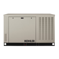
7.9 Connection Box Reassembly
1. Attach the ground from the connection box to the
stator housing.
2. Carefully position the connection box on the skid
and secure with four mounting bolts.
3. Attach the connection box ground strap to the skid.
4. Open the saddle box lid on the alternator and pull
the alternator leads into the connection box.
5. Connect the following alternator harness leads
inside the connection box:
D Auxiliary power, exciter field leads and voltage
sensing leads
D Alternator leads on the circuit breaker
6. Connect the following leads inside the connection
box:
D Load leads on the circuit breaker
D External leads on TB1 such as the transfer
switch or load control module connections
D 120 V utility power leads for the battery charger
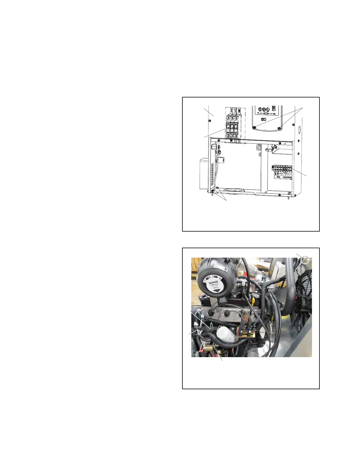
7. Connect the following generator wire harness
connections on the radiator and in the engine
compartment:
D Engine harness connector
D Coolant level sensor, located at the top of the
radiator
D Radiator fans
D Engine compartment fan
D Engine compartment temperature sensor
D Quick connection leads on the ballast resistor
Note: The ballast resistor is located on the
alternator saddlebox. Remove the cover to
access the ballast resistor connections.
D Quick connection leads on the fuel solenoid
valves
D Generator wire harness leads on the starter
motor
8. To attach the controller:
a. Connect the wire harness and ethernet plugs
on the back of the controller.
b. Position the controller.
c. Use the mounting bolts to secure the controller.
9. Position and secure the upper and lower access
covers.
1. Connection box
2. Controller mounting
bolts
3. TB1
4. Mounting bolts, qty. 4
5. Circuit breaker
4
1
5
2
3
Lower access panel removed.
Figure 7-10 Connection box
558866
1. Coolant level sensor
2. Starter motor
3. ECM interface
4. Leads and battery
grounds
3
2
1
4
Figure 7-11 Wire Harness Connections
 Loading...


