TP-6907 5/16 81Section 6 Component Testing and Adjustment
6.2 Voltage Connections
Generator sets equipped with a 12-lead alternator are
reconnectable to the following configurations: Delta,
Low Wye, and High Wye. See the generator set
Installation Manual or the alternator service manual for
reconnection instructions and diagrams. Generator
sets equipped with a 4-lead alternator are not
reconnectable.
Setting the system voltage above 300 VAC will cause
the controller to automatically switch from a low wye to a
high wye configuration. Use Kohlerr SiteTecht
Software or the controller keypad to update the System
Voltage and Phase Connection when the alternator
voltage connections are changed.
6.3 Additional Alternator Service
Information
Refer to the alternator service manual for additional
alternator testing and service information.
6.4 Voltage Adjustments
Hazardous voltage.
Can cause severe injury or death.
Operate the generator set only when
all guards and electrical enclosures
areinplace.
Moving parts.
WARNING
Testing live electrical circuits. Hazardous voltage or
current can cause severe injury or death. Have trained and
qualified personnel take diagnostic measurements of live
circuits. Use adequately rated test equipment with electrically
insulated probes and follow the instructions of the test
equipment manufacturer when performing voltage tests.
Observe the following precautions when performing voltage
tests: (1) Remove all jewelry. (2) Stand on a dry, approved
electrically insulated mat. (3) Do not touch the enclosure or
components inside the enclosure. (4) Be prepared for the
system to operate automatically.
(600 volts and under)
Short circuits. Hazardous voltage/current can cause
severe injury or death. Short circuits can cause bodily injury
and/or equipment damage. Do not contact electrical
connections with tools or jewelry while making adjustments or
repairs. Remove all jewelry before servicing the equipment.
Note: For voltage calibration instructions, see
Section 3.7.
6.4.1 Voltage Adjustments Using
SiteTech
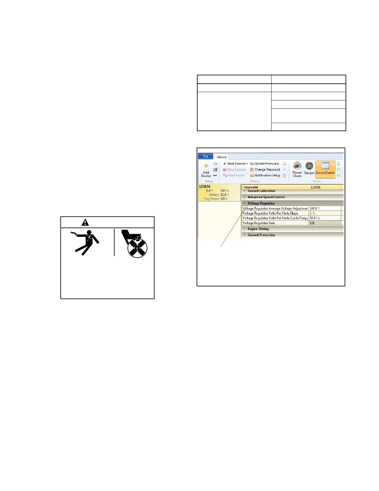
The SiteTech parameters used to adjust the voltage in
the following procedures are shown in Figure 6-2 and
Figure 6-3.
SiteTech Grou p Parameter
Genset System Configuration Genset System Voltage
Voltage Regulator Average Voltage Adjustment
Volts per Hertz Slope
Volts per Hertz Cut-in
Frequency
Voltage Regulator Gain
Figure 6-2 SiteTech Parameters for Voltage
1
tp6907
1. Voltage regulator parameter group
Figure 6-3 Voltage Regulator Parameter Group in
SiteTech
 Loading...


