TP-6907 5/16 79Section 6 Component Testing and Adjustment
Section 6 Component Testing and Adjustment
6.1 Alternator Excitation
Troubleshooting
This section covers the basic procedures for
troubleshooting alternator excitation. For advanced
service procedures, refer to the alternator service
manuals listed in the introduction of this manual.
Hazardous voltage.
Can cause severe injury or death.
Operate the generator set only when
all guards and electrical enclosures
areinplace.
Moving parts.
WARNING
Servicing the generator set when it is operating. Exposed
moving parts can cause severe injury or death. Keep
hands, feet, hair, clothing, and test leads away from the belts
and pulleys when the generator set is running. Replace
guards, screens, and covers before operating the generator
set.
6.1.1 Low to No Voltage Operation
This section covers the operation of the alternator
excitation and troubleshooting information for low or no
voltage output. Before beginning the test procedures,
read all safety precautions at the beginning of this
manual. Many of the test procedures include additional
safety precautions.
Before beginning the troubleshooting steps in this
section, verify that the controller is trying to excite the
field on the generator. This can be determined by
observing that the generator set is in one of the following
states:
D Running
D Unloaded full speed exercise
D Unloaded cycle diagnostic mode (only during the 3
minute full speed portion of the test)
If the generator state is in one of the following states, the
controller is deliberately not exciting the alternator field
and no voltage is produced:
D Cooldown
D Unloaded cycle diagnostic mode (except during
the 3 minute full speed portion of the test)
To further isolate the cause of low or no output voltage:
1. Verify that the generator frequency is above the
cut-in frequency for the volts/Hz curve. See
Section 6.4.3.
2. Verify that the RDC2 controller is configured to
output the correct voltage and that it is metering
accurately. Check the system voltage setting and
the voltage calibration.
3. Open the line circuit breaker to see if the voltage
recovers (the generator may be feeding a short
circuit).
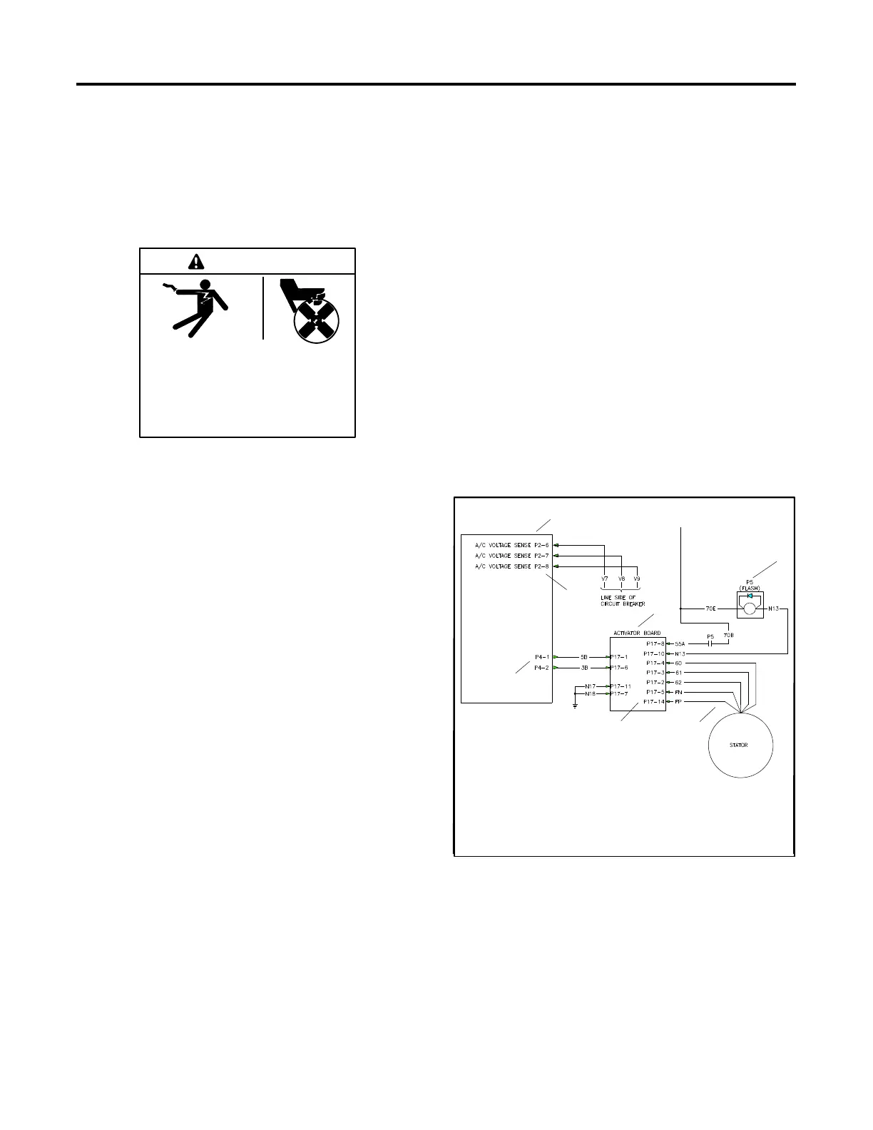
ADV-8554
1. RDC2 controller
2. P2 plug
3. Activator board
4. Field flash relay
5. Stator windings
6. P17 plug
7. P4 plug
RDC2
Controller
5
2
3
6
1
4
7
Figure 6-1 24RCL Single-Phase or Three-Phase
Generator Schematic
 Loading...


