TP-6811 7/16 27Section 3 Controller
Section 3 Controller
3.1 Introduction
The RDC2 controller manages the operation of the
generator set, a Model RXT transfer switch (if
equipped), an optional Programmable Interface Module
(PIM) and an optional load management device. See
the generator set Operation Manual for controller
operation instructions.
This section covers adjustment and replacement of the
RDC2 controller. See Section 5 for troubleshooting
procedures.
See the service view and Figure 3-3 for the controller
location.
3.2 SiteTech Software
Many procedures in this manual require the use of a
personal computer (or laptop) with Kohlerr SiteTecht
software to change controller settings or update
firmware. SiteTech software is available to
Kohler-authorized distributors and dealers. See the
SiteTech Operation Manual, TP-6701, for general
software operation instructions.
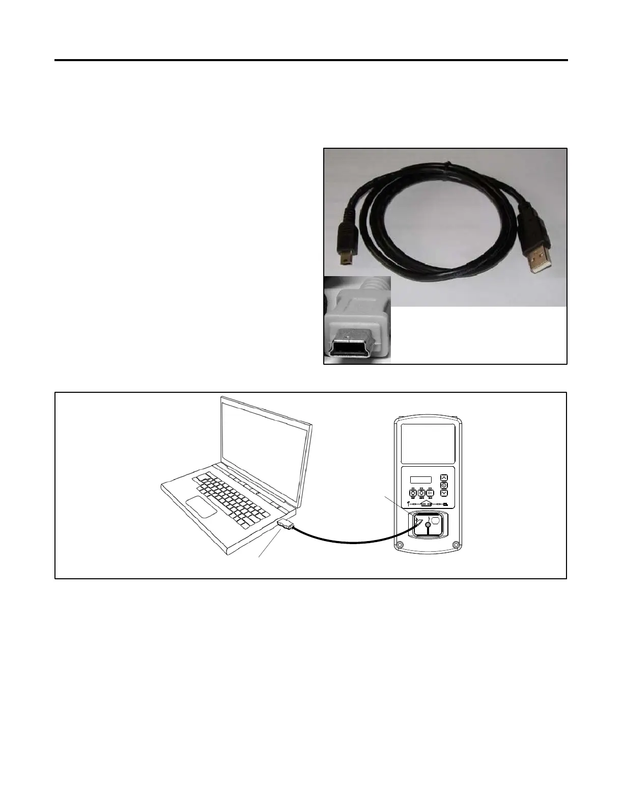
Use a USB cable to connect the personal computer
directly to the device. See Figure 3-2. The USB cable
must have a male USB A connector on one end and a
male mini-B connector on the other and must be less
than 5 m (16.4 ft.) long. See Figure 3-1.
Detail, mini-B connector
Figure 3-1 USB Cable
TP-6805
2
1
1. USB cable connection to PC 2. USB cable connection to controller
Figure 3-2 USB Connection (RDC2 controller shown)

 Loading...


