EasyManua.ls Logo

Kohler 48RCL User Manual

Kohler 48RCL
112 pages
To Next Page IconTo Next Page
To Previous Page IconTo Previous Page
Page #87 background imageLoading...
Page #87 background image
TP-6811 7/16 87Section 6 Component Testing and Adjustment
6.8.1 Fuel Solenoid Valves
Two 12 VDC solenoid valves are mounted upstream of
the engine on the generator set skid. See Figure 6-14.
The fuel solenoid valves provide automatic fuel on/off
control. See Figure 6-14. The engine starting battery
powers the solenoid valve and the engine starting
controls open the valves when the engine cranks or
runs.
Fuel Valve Operation Test Procedure
1. Disconnect the positive (+) battery lead from the
gas valve terminal.
2. Apply 12 VDC to the gas valve terminal and listen
for an audible click, indicating that the valve
actuates.
3. Replace the gas valve if it does not actuate in
step 2.
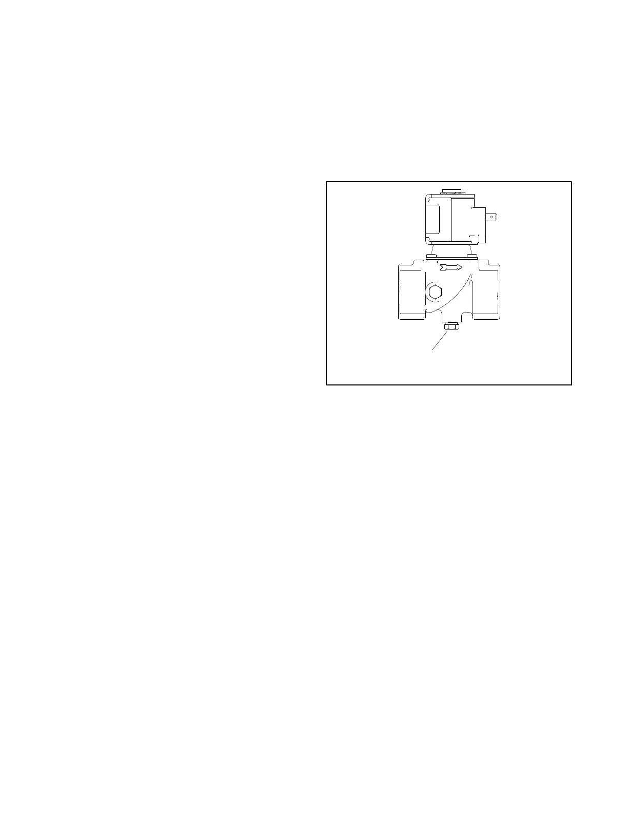
6.8.2 Checking the Fuel Pressure
Connect a pressure gauge or manometer to the port on
the bottom of the second (downstream) fuel solenoid
valve to measure the fuel pressure to the engine. See
Figure 6-14 and Figure 6-15.
Measure the fuel pressure with the generator set
running at rated load. The fuel pressure should b e
5--11 in. water column or 1.2--2.7 kPa. Contact the fuel
supplier if the inlet pressure is not within the specified
range.
1
GM82797
1. Fuel pressure port
Figure 6-15 Fuel Solenoid Valve

Table of Contents

Other manuals for Kohler 48RCL

Questions and Answers:

Kohler 48RCL Specifications

General IconGeneral
BrandKohler
Model48RCL
CategoryInverter
LanguageEnglish

Summary

Service

Safety Precautions and Instructions

Accidental Starting and Battery Safety

Procedures to prevent unintended generator startup and hazards associated with batteries.

Engine Fire and Exhaust System Safety

Warnings regarding fuel system, engine fluids, fire risks, and carbon monoxide hazards.

Fuel System and Noise Hazards

Precautions for fuel handling and safety measures related to hazardous noise levels.

Electrical Safety and Testing Precautions

Guidance on safe practices for electrical connections, testing, and welding.

Heavy Equipment and Hot Parts Safety

Safety measures for lifting equipment and handling hot components.

Important Notices

Important notes related to Canadian installations and electrostatic discharge.

Introduction to Manual

Related Literature and Manuals

Catalog of associated manuals providing additional operational and service information.

Service Assistance and Support

Section 1 Specifications Overview

Introduction to Specifications

Guidance on using specification sheets and nameplates for model-specific data.

Controller Specifications (RDC2)

Environmental and voltage requirements for the RDC2 controller.

Engine Service and Specifications

Details on engine types used and references to engine service manuals.

Alternator Specifications

Key alternator details including manufacturer, exciter type, and insulation class.

Torque Specifications Guidance

Recommendations for torque values for alternator and engine assembly.

Service Views (38RCL Model)

Visual identification of components on the 38RCL generator set.

Section 2 Scheduled Maintenance

General Maintenance Practices

Fundamental safety and service guidelines applicable to all maintenance.

Maintenance Service Schedule

A comprehensive schedule detailing maintenance operations based on operating hours or time.

Lubrication System Maintenance

Instructions for oil specifications, checking, adding, and changing oil and filter.

Air Cleaner Maintenance

Procedures for inspecting, cleaning, and replacing the air cleaner element.

Exhaust System Inspection

Guidelines for inspecting exhaust system components for leaks and damage.

Ignition System Maintenance

Procedures for servicing and checking spark plugs, including gap and condition.

Battery Maintenance and Safety

Safety measures and procedures for battery care, including electrolyte and short circuits.

Fuel System Maintenance Procedures

Guidelines for maintaining the fuel system, including leak checks and component cleaning.

Section 3 Controller Operations

Controller Introduction and Software

Overview of the RDC2 controller's role and SiteTech software for configuration.

Controller Parameters Overview

Explanation of adjustable parameters and how to change them via PC or controller.

Controller Firmware Updates

Procedure for updating controller firmware using a PC and USB cable.

Controller Replacement Procedure

Step-by-step guide for replacing the RDC2 controller with a new unit.

Controller Setup Process

Initial setup steps for the controller after installation, covering essential parameters.

Voltage Calibration Methods

Step-by-step instructions for calibrating generator voltage via keypad or software.

Setting the OnCue Password

Steps to reset and set the OnCue password for generator monitoring.

Section 4 Cooling System

General Cooling System Overview

Basic principles of the closed-loop engine cooling system and its components.

Radiator and Hose Inspection

Procedure for cleaning radiator fins and inspecting hoses for damage or leaks.

Engine Thermostat Information

Details on the thermostat's location and operating temperature rating.

Cooling System Inspection and Coolant Checks

Guidelines for general cooling system checks and maintaining coolant levels.

Draining and Flushing Cooling System

Procedures for draining, flushing, and cleaning the cooling system.

Filling the Cooling System

Steps for refilling the cooling system with the correct coolant mixture.

Pressure Cap Information

Details on the pressure cap's function and replacement rating.

Cooling Fan Operation and Troubleshooting

Description of cooling fan operation and a guide to troubleshooting fan issues.

Section 5 Troubleshooting

Introduction and Initial Checks

General advice and essential preliminary checks for effective troubleshooting.

Electronic Start Sequence Theory

Explanation of the electronic sequence of operations during engine starting.

Circuit Protection and Fuel System Issues

Procedures for checking circuit protection and diagnosing fuel system problems.

Controller Service Access and Fault Messages

Accessing the controller and interpreting fault messages for diagnostics.

System Status Messages

Interpretation of status messages displayed by the controller indicating system state.

Generator Set Troubleshooting Guides

Tables covering common problems related to starting, operation, and stopping.

Controller Troubleshooting

Common issues with the controller display, communication, and relays.

Section 6 Component Testing and Adjustment

Alternator Theory and Excitation Troubleshooting

Explanation of alternator operation and steps for troubleshooting excitation.

Low Voltage and Overvoltage Diagnosis

Diagnostic steps for low voltage, erratic regulation, and overvoltage conditions.

Voltage Connections and Reconnection

Information on reconnecting alternator leads for different voltage configurations.

Additional Alternator Service Information

References to the alternator service manual for further details.

Voltage Adjustments

General guidance and safety precautions for adjusting generator voltage.

Volts/Hz Slope and Cut-In Frequency Settings

Explanation of Volts/Hz curve settings and their impact on generator performance.

Voltage Regulator Gain Adjustment

Information on voltage regulator gain settings and their effect on voltage stability.

Frequency Adjustment and Governor Settings

How to adjust generator frequency and engine speed settings.

Generator Set Switches and Sensors

Testing procedures for engine compartment temperature sensor and other switches.

Fuel System Testing

Description of the fuel system and procedures for testing solenoid valves and pressure.

Section 7 Disassembly/Reassembly

Initial Steps and Enclosure Removal

Preliminary safety steps and instructions for removing enclosure panels.

Connection Box and Other Components Removal

Steps for removing the connection box and other components near the alternator.

Alternator Component Identification

Identification of the main components of the alternator assembly.

Section 8 Diagrams and Schematics

Schematic Diagram References

List of schematic diagram sheets, their drawing numbers, and page locations.

Wiring Diagram References

List of wiring diagram sheets, their drawing numbers, and page locations.

Appendix A Abbreviations

Appendix B Common Hardware Application Guidelines

Appendix C General Torque Specifications

Appendix D Common Hardware Identification

Related product manuals