TP-6391 9/08 17Section 3 Troubleshooting
Section 3 Troubleshooting
3.1 Introduction
Corrective action and testing in many cases requires
knowledge of electrical systems and electronic circuits.
Have an authorized distributor/dealer or trained service
technician perform testing and service.
Refer to the Engine Service Manual, TP-6002 and
TP-6008, for engine service information.
The first step in troubleshooting the generator set
controls is to verify that the controller is correctly
configured for the generator set. The Generator Set
Installation Manual explains how to check and change
the controller configuration.
If the troubleshooting procedures in this section identify
a bad part, refer to the parts catalog for replacement part
numbers. See the List of Related Materials in the
Introduction for the parts catalog number.
3.2 Initial Checks
When troubleshooting, always check for simple
problems first. Check for the following common
problems before replacing parts:
D Loose connections or damaged wiring.
D Dead battery.
D Fault shutdown. Check for a fault code on the
ADC 2100 display. Section 4.5 describes the
warning and shutdown fault codes.
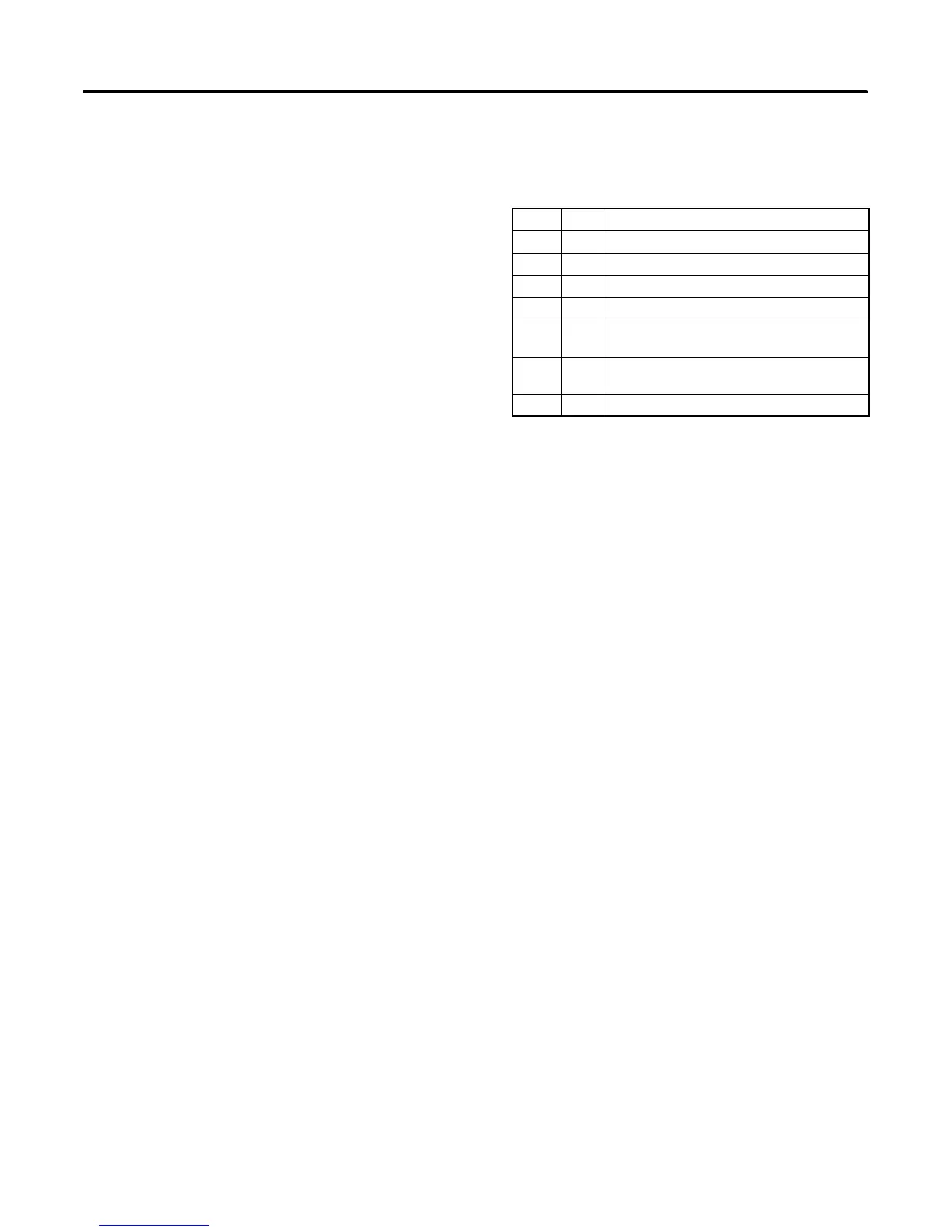
D Blown fuses. See Figure 3-1 for fuse identification.
Always check and replace the fuses before replacing
other components. See Figure 2 for fuse part
numbers.
Label Amp Fuse
F1 10 Auxiliary winding
F2 10 Controller
F3 10 Customer connection
F4 15 Coils/injectors
F5 15 ECM, O
2
sensor, fuel pumps, and temp.
sender
F6 15 Voltage regulator and battery charging
alternator
F7 20 Starter motor and crank solenoid
Figure 3-1 Fuse Identification
D Incorrect controller settings. Always check the
controller configuration settings before replacing the
controller. Section 4.11 explains how to check and
change the controller settings.
3.3 Troubleshooting C hart
Use the following table(s) as a reference i n
troubleshooting individual problems. Generator set
faults are listed in groups and include likely causes and
remedies. The simplest and most likely causes of the
problem are listed first; follow the recommendations in
the order shown. The reference column provides
additional sources of information in this and related
manuals regarding the problem and solution.
Note: In the following table(s), O/M refers to the
Operation Manual, I/M refers to the Installation
Manual, and S/M refers to the Service Manual.
 Loading...


