TP-6391 9/08 35Section 4 Controller
4.6 Relay Interface Board (RIB)
The relay interface board (RIB) contains the K2 crank,
K3 flash, and K5 run relays. Three LEDs indicate relay
operation. See Figure 4-9.
Refer to the schematic diagram in Section 7 for the relay
board connections.
The RIB is protected by a 10 amp fuse (F2). If the fuse
blows repeatedly, disconnect the board leads one at a
time to identify the cause of the blown fuse:
D Lead 70A
D Leads FP and FN at the rotor
If the fuse continues to blow and disconnecting
components did not identify the cause, remove the
leads from the P14 connector using a pin pusher, part
#241918 (large) or 241919 (small). If replacing the
leads does not solve the problem, replace the RIB.
The individual relays are not replaceable. If one or more
relays are faulty, replace the entire RIB.
To replace the RIB:
1. Disconnect P14 and the brush leads FP and FN.
2. Pull the board straight off the mounting stand-offs.
3. Snap the new board onto the stand-offs and
reconnect P14 and the brush leads.
4
GM29671-A
1. K1 common fault relay (optional)
2. K2 crank relay (standard)
3. K3 flash relay (standard)
4. K4 auxiliary run relay (optional)
5. K5 run relay (standard)
6. P14, engine harness connection (standard)
7. P13, connection to optional relay harness (optional)
FLASH
K3
VBAT
D3D1 D2
K1
FLASH
LED2
CRANK
LED3
D4
D5
T2
FP
9
FN
T1
7
RUN
R
R
R
LED1
R1
R2
R3
K4
46
P13
P14
K2
CRANK
3
K5
1
RUN
FAU LT
COMMON
3
1
D7
D6
AUX
RUN
5
1
2
3
7
6
Figure 4-9 Relay Board
4.7 CO S ensor Module
The CO sensor module is located behind the ADC 2100.
Replace the CO sensor module every two years. See
Figure 4-10.
Note: The CO sensor module is equipped on generator
sets with serial number 2085259 and later.
GM463262-
Figure 4-10 CO Sensor Module
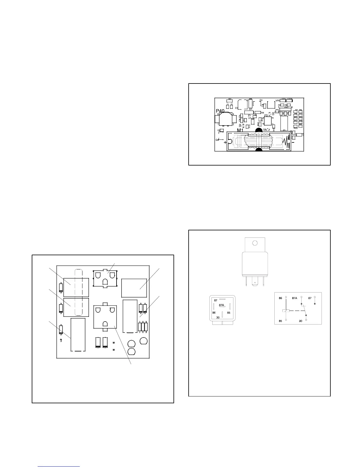
4.8 K5 Main P ower Relay
The K5 relay powers the ECM, injector, c oils, governor
assembly/throttle body, TMAP sensor, and O2 sensor.
See Figure 4-11.
GM28787-K
SCHEMATIC
(sINGLE POLE DOUBLE THROW)
Rated Voltage 12 VDC
Operating Current 133 mA
Coil Resistance 90 ± 10 ohms
Pull-In Voltage < 8 V
Release Voltage 1.2 V
Max. Operating Voltage 15.6 V
Figure 4-11 K5 Relay Specs
 Loading...


