TP-6391 9/08 59Section 6 Generator Disassembly/Reassembly
Section 6 Generator Disassembly/Reassembly
6.1 Disassembly
Disconnect all of the external connections—battery
cables at the battery (negative (--) lead first), AC-output
leads, remote interface connector. Close the seacock.
Remove the water line at the seawater pump, fuel line at
the fuel pump filter inlet, and exhaust line at the catalyst
assembly. Remove the sound shield enclosure, if
equipped. Observe all of the safety precautions listed at
the beginning of this manual during the
disassembly/reassembly procedures.
Note: Because this manual covers several models, the
procedure for disassembly may vary because of
product updates and the assembly variations.
Note: Mark leads that are disconnected. Refer to the
wiring diagrams in Section 7 during reassembly.
1. Place the generator set master switch in the OFF
position.
2. Disconnect power to the battery charger, if
equipped.
3. Disconnect the generator set engine starting
battery, negative (--) lead first.
Accidental starting.
Can cause severe injury or death.
Disconnect the battery cables before
working on the generator set.
Remove the negative (--) lead first
when disconnecting the battery.
Reconnect the negative (--) lead last
when reconnecting the battery.
WARNING
4. Disconnect wiring harness plugs P1, P15, and P16
from the ADC 2100.
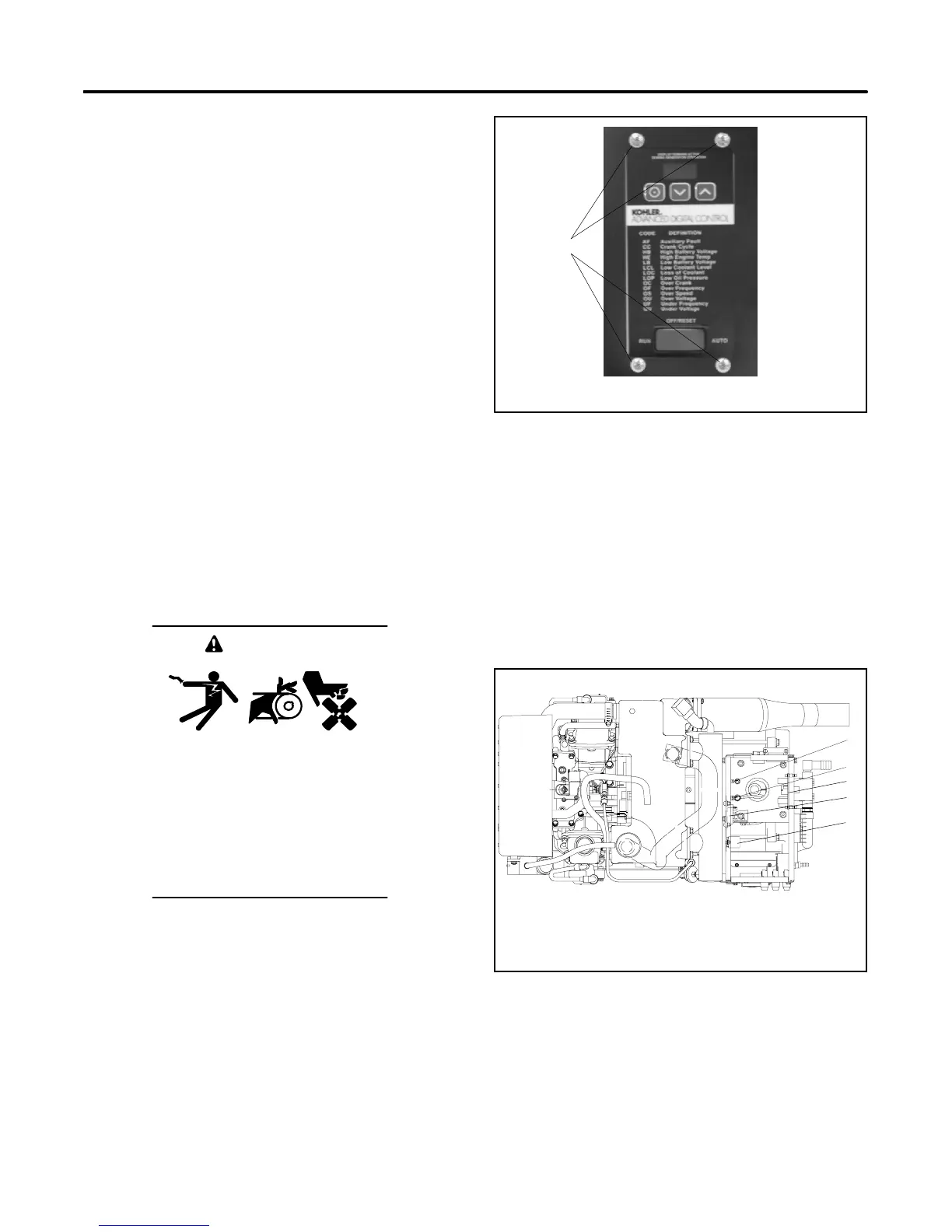
5. Loosen and remove the four controller mounting
screws at the front of the controller. See
Figure 6-1. Remove the controller.
1
tp6196
1. Controller mounting screws (4 ea.)
Figure 6-1 ADC 2100 Mounting Screws
6. Disconnect the generator output leads from the
circuit breaker and disconnect QCON1 from the F1
fuse.
7. Disconnect the LO and GRD lead connections.
See Figure 6-2.
8. Disconnect the FP and FN leads.
9. Remove the SCR module and relay board as
necessary. See Figure 6-2.
GM39685D-J
1. LO stud
2. Ground stud
3. Relay interface board (RIB)
4. SCR module
5. K5 main power relay
Top View
1
2
3
4
5
Figure 6-2 Advanced Digital Control (ADC 2100)
 Loading...


