TP-6391 9/0862 Section 6 Generator Disassembly/Reassembly
6.2 Collector Ring and Bearing
Replacement
1. Unsolder the collector ring leads from the collector
ring terminals.
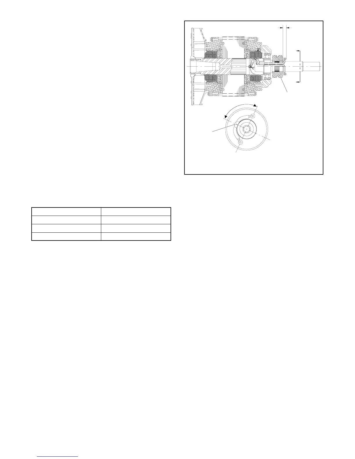
2. Remove the collector rings with a three-jaw puller.
3. Remove the bearing with a three-jaw puller.
4. Press the new bearing onto the rotor shaft.
5. Align the collector ring keyway with the keyway on
the rotor shaft. See Figure 6-8.
6. Press the new collector rings onto the rotor shaft.
Note: The new collector rings must be turned down to a
finish of 32 micro inches using a lathe and
commutator stones. Turn down the collector
rings on the rotor shaft.
7. Solder the leads onto the collector ring terminals.
The connection is not to exceed 9.65 mm (0.38 in.)
beyond the collector rings. See Figure 6-8.
8. Test to ensure continuity at the collector rings.
Min. diameter mm (in.) 57.15 (2.250)
Max. finish 32 micro inches
Max. eccentricity mm (in.) 0.08 (0.003)
Max. out-of-round mm (in.) 0.01 (0.0002)
Figure 6-7 Collector Ring Dimensions
598695
1. Collector ring leads
2. Keyways
View A-A
A
A
1
2
90°
.38 maximum
(as soldered)
Figure 6-8 Rotor Assembly
 Loading...


