TP-6391 9/08 23Section 4 Controller
Section 4 Controller
4.1 Introduction
This section describes the operation and replacement of
the ADC 2100 controller. Controller configuration and
adjustment are explained in Section 4.11. See Section 3
for troubleshooting procedures.
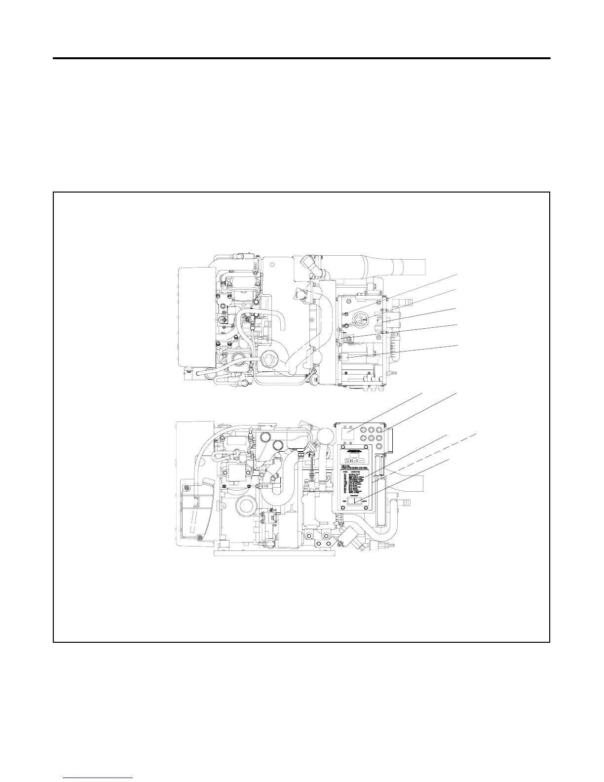
See Figure 4-1 for the locations of the ADC 2100
controller and related components.
A relay interface board (RIB) is used with the ADC
controller. Section 4.6 describes the relay interface
board.
A silicon controlled rectifier (SCR) module works with
the controller to regulate the output voltage. See
Section 4.9.
GM39685D-J
1. LO stud
2. Ground stud
3. Relay interface board (RIB)
4. SCR module
5. K5 main power relay
6. Line circuit breaker panel (load connection)
7. Fuse location. See Section 5.12
8. ADC 2100 controller
9. CO sensor module (available on units with serial number
2085259 and later)
10. Generator set master switch
Service-Side View
Top View
1
2
6
7
8
10
3
4
5
9
Figure 4-1 Advanced Digital Control (ADC 2100)
 Loading...


