TP-6137 5/0342 Section 8 Controller Troubleshooting
8.1 General
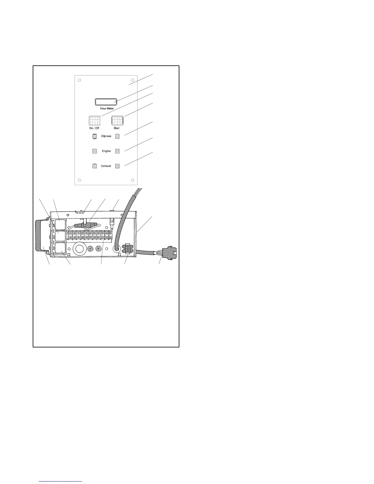
The following section covers the controller
troubleshooting procedure. Refer to Figure 8-2 to
identify the controller components.
1
3
4
5
6
2
7
1. Control panel
2. Hourmeter
3. On/off switch
4. Start switch
5. Green/red oil pressure
LEDs
6. Green/red engine water
temperature LEDs
7. Green/red exhaust
temperature LEDs
8. Control box
9. 25 amp fuse
10. 10 amp fuse
11. Bridge rectifier
12. K1 relay
13. K2 relay
14. K3 relay
15. Engine voltage regulator
16. Electrical connection plate
17. Harness control box (to
engine connector)
18. Harness control box (to STD
panel connector)
LO
GRD
BH1
F1
K3
K2
K1
P1
TB1
VR
F2
P3
8
910111213
18161415 17
Figure 8-2 Controller Internal Components
8.1.1 On/Off Switch
After pressing the On/Off switch on the control panel
(local or remote), two green LEDs and one red LED (oil
engine) light. This operation energizes the control panel
and permits DC to the K2 relay. This in turn energizes
the fuel solenoid (FS) and the fuel pump (FP) because
the normally open contacts of the K2 relay close.
8.1.2 Start
Press the START switch (local or remote) the K1 relay
energizes. The normally open K1 contacts close
allowing DC to the normally open contacts of the starter
motor’s solenoid (S). The energized starter starts the
generator set’s engine.
8.1.3 Run
After reaching correct engine and generator set
performance, the two generator set wires marked
10 and 11 energize the K3 relay (AC crank disconnect)
that opens its normally closed contacts.
DC supplied to the starter is interrupted, every starting
operation is eliminated.
The generator set wires marked C1 and C2 connect at
the capacitor supplying AC. As it gives or receives
current in accordance with variable loads, its capacity
changes to hold the correct AC voltage value.
When good engine oil pressure operation is reached,
the normally closed contacts of the low oil pressure
(LOP) switch close. The red LED on the control panel
cuts off and the green LED lights.
If all three green LEDs on the control panel are lit at the
same time, good engine performance is achieved and
AC is supplied to the windings L1, L2, L3 and L4.
8.1.4 On/Off Switch (Stop)
If the On/Off switch (local or remote) is repressed, the K2
relay deenergizes. The fuel solenoid (FS) and fuel
pump (FP) do not receive DC, the normally open K2
contacts reopen and the engine stops.

 Loading...

