TP-5982 4/0620 Section 4 Exhaust System
1
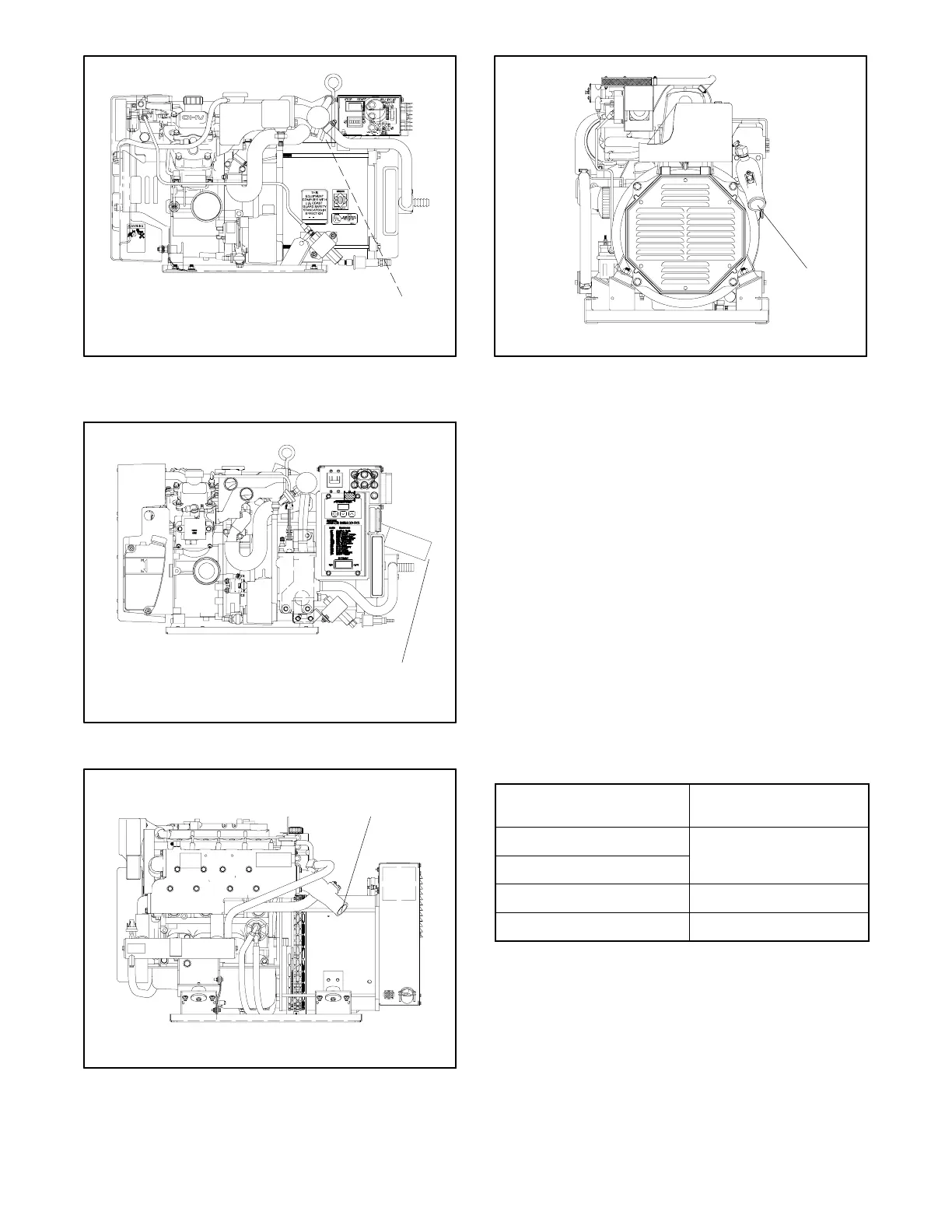
ADV-6395A-K
1. Water/exhaust outlet located on opposite (nonservice) side
Figure 4-1 Mixer Elbow/Exhaust Connection
(5/7.3E)
1
ADV-7025A-A
1. Water cooled exhaust outlet
Figure 4-2 Water Cooled Exhaust Outlet (5/7.3ECD)
1. Water/exhaust outlet located on opposite (nonservice) side
1
ADV6817-B
Figure 4-3 Mixer Elbow/Exhaust Connection
(10/13/15EG and 13/15EGZ)
1
GX-250000-
1. Water/exhaust outlet
Figure 4-4 Mixer Elbow/Exhaust Connection
(15/20C)
Locate the exhaust outlet at least 10 cm (4 in.) above the
waterline when the craft is loaded to maximum capacity.
Install an exhaust port with flap at the exhaust (transom)
outlet to prevent water backup in following seas or when
moving astern (backward). A lift in the exhaust piping
before exiting the boat prevents backwash. See
Figure 4-6, Item 1. Support the exhaust lines to prevent
the formation of water pockets.
Exhaust system guidelines for various generator set
locations follow. Information and illustrations of stern-
(rear) exhaust installations also apply to side-exhaust
installations. Where exhaust lines require passage
through bulkheads, use port- (left) or starboard- (right)
side exhaust outlets. This is especially true of
applications in which long exhaust lines to the transom
(rear) could cause excessive back pressure. See
Figure 4-5 for allowable back pressures.
Model
Allowable Exhaust
Back Pressure
5/7.3E and 4/6EF
5/7.3ECD and 4/6EFCD
< 1.42 psi (3 in. Hg)
10/13/15EG and 13/15EGZ < 1.47 psi (3 in. Hg)
15/20C and 12.5/16CF < 2.94 psi (6 in. Hg)
Figure 4-5 Allowable Exhaust Back Pressures
 Loading...
