TP-5982 4/06 35Section 6 Electrical System
6.7 Wiring
Use only stranded copper wire. Conform to USCG
Regulations 183.425 through 183.460 for wire gauges
and insulation, conductor temperature ratings, sheath
stripping, conductor support and protection, conductor
terminals and splices, and overcurrent protection
(circuit breakers, fuses). Use rubber grommets and
cable ties as necessary to protect and secure the wire
from sharp objects, the exhaust system, and moving
parts.
6.8 Remote Start Switch
Connection
Kohler Co. offers several remote panels for connection
to the generator set. Contact your local Kohlerr
distributor/dealer for further detailed descriptions. See
Figure 6-5, Figure 6-6, or Figure 6-7 for the location of
the remote start panel connection to the generator set
controller. Kohler Co. also offers wiring harnesses in
various lengths with a connector keyed to the controller
box connector. A “pigtail” harness is also offered which
includes the appropriate connector on one end and has
pigtails that the installer can use to connect to a
customer-supplied start/stop switch or separate lights
and hourmeter. Consult current wiring diagrams, ADVs,
and instruction sheets for connection information and
details.
5/7.3ECD, 4/6EFCD, 10/13/15EG, and 13/15EGZ
Models. These models use a 12-pin connector for the
remote interface connection. See Figure 6-6 or
Figure 6-7 for the connector’s location. See Figure 6-8
for the correct customer-supplied plug and pin part
numbers.
1
DA-250000-H
1. Controller remote connector
Figure 6-5 Controller Remote Connector (Typical)
5/7.3E, 4/6EF, 15/20C, and 12.5/16CF
Models
1
ADV6843b-a
1. Remote interface connector
Non-Service Side
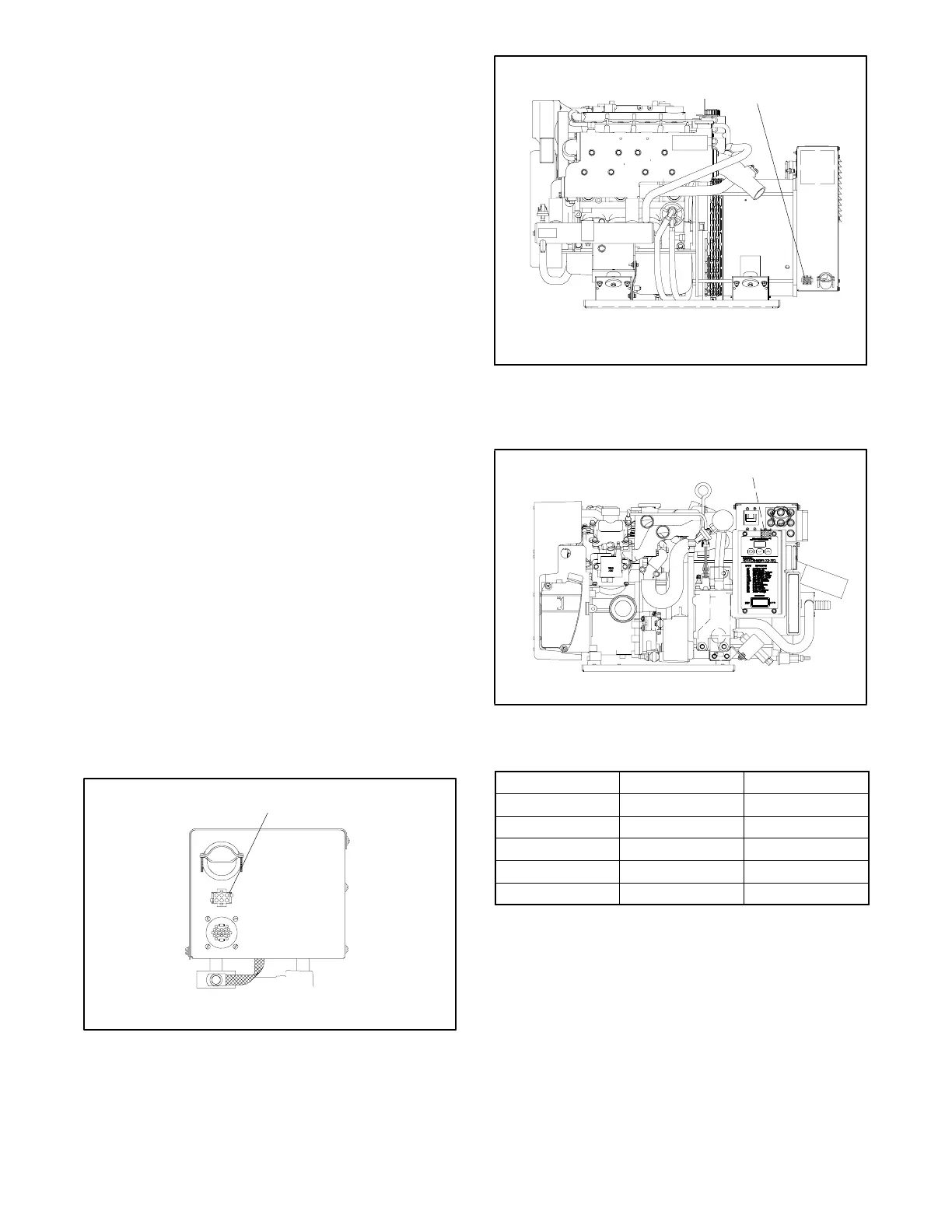
Figure 6-6 Remote Interface Connector,
10/13/15EG and 13/15EGZ Model
Shown
1
ADV7025A-A
1. Remote interface connector (located on the non-service side)
Figure 6-7 Remote Interface Connector, 5/7.3ECD
Model Shown
Component Amp Part No. Kohler Part No.
Plug 350735-1 229998
Pin 350218-6 241618
Cable Seal 794280-1 GM29252
Interface Seal 794279-1 GM29507
Cavity Plug 770377-1 GM28769
Figure 6-8 Connector Components
(5/7.3ECD, 4/6EFCD, 10/13/15EG, and
13/15EGZ Models)
Note: Gauge senders. Gauge senders are available
for most generator sets. If using gauges, be sure
they are compatible with generator set senders.
Gauges/senders are available as a service item
from authorized Kohler service
distributors/dealers.
 Loading...
