TP-5982 4/06 37Section 7 Installation Drawings
Section 7 Installation Drawings
Use the drawings in this section for installation
purposes. Consult the supplier and verify that the
drawings are the most current for your specification.
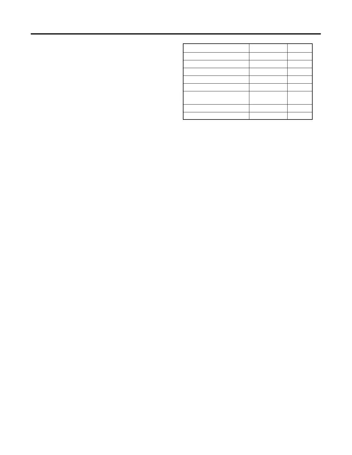
Installation drawings show exhaust outlet locations, fuel
inlet connections, siphon break locations, and battery
connections. See Figure 7-1 for installation drawing
identification.
Model No. Drawing Page
5/7.3ECD and 4/6EFCD ADV-7025A 38
with Sound Shield ADV-7025B 39
5/7.3E and 4/6EF ADV-6395A 40
with Sound Shield ADV-6395B 41
15/20C and 12.5/16CF ADV-6382A 42
15/20C and 12.5/16CF
PTO Kit
ADV-6382B 43
10/13/15EG ADV-6817A 44
13/15EGZ with PTO ADV-6817B 45
Figure 7-1 Installation Drawings
 Loading...
