TP-5982 4/0622 Section 4 Exhaust System
4.2.2 Mid/Below Waterline Installation
Follow USCG regulations for installing an antisiphon
provision to prevent raw water entry into the engine.
Use the siphon break if the exhaust manifold outlet is
located less than 23 cm (9 in.) above the waterline when
the craft is loaded to maximum capacity. Install the
siphon break at least 31 cm (1 ft.) above the waterline.
To install, see the instructions provided with the siphon
break kit.
Note: Failure to properly install a siphon break will
cause engine damage and may void the
warranty.
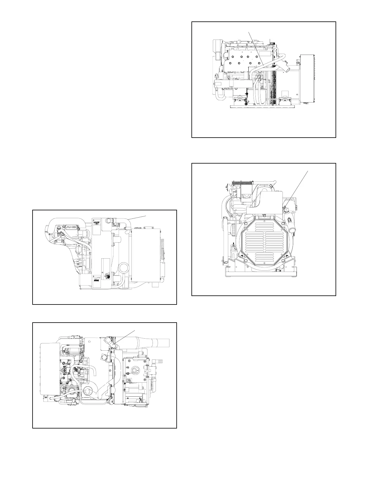
Locate the siphon break above the highest point in the
exhaust line between the heat exchanger and the
exhaust mixer. See Figure 4-7, Figure 4-8, Figure 4-9,
or Figure 4-10 for siphon break connection. Support the
siphon break and hoses to maintain their position and
function. Mount the siphon break directly vertical of its
connection to the generator set where possible.
Otherwise, allow a slight offset to clear stringers or other
permanent structures. Protect the siphon break air inlet
from dirt and debris.
1
GY-250000-
CHECK ZINC ANODE
EVERY 100 HOURS
OR3MONTHS.
carbon monoxide.
Can cause severe
nausea, fainting,
or death.
Completlelyseal off
compartmentto
maintainvapor tightness
toliving space.
Seeoperator’s manual
forcomplete
installationinstructions.
WARNING
Hotengine
andexhaust system.
Cancause severe burns.
Donot work on
generatorset until
unitis allowed tocool.
CAUTION
Beforeremoving cap
stopgenerator,
allowto cool and
loosencap to
relievepressure.
Fillsystem before
startingunit.
WARNING
Hotcoolant and
steam.
Cancause severe
burnsand
personalinjury.
1. Connect siphon break and hardware
Top View
Figure 4-7 Siphon Break Connection (5/7.3E Model)
1
GM39685D-
1. Connect siphon break and hardware
Top View
Figure 4-8 Siphon Break Connection (5/7.3ECD
Model)
1. Connect siphon break and hardware
1
GM34482D-
Nonservice-Side View
Figure 4-9 Siphon Break Connection (10/13/15EG
and 13/15EGZ Model)
1
GX-250000-
1. Connect siphon break and hardware
Generator-End View
Figure 4-10 Siphon Break Connection (15/20C Model)
Mount a typical silencer’s base no more than 1.2 m (4 ft.)
below the highest point in the exhaust line. Attach a
separate wood mounting base to the hull stringers or
other suitable structures. Use the silencer
manufacturer’s recommendation for securing the
silencer to the hull. Mount the silencer with outlet not
more than 3 m (10 ft.) horizontally from the engine
exhaust manifold outlet. Use a USCG-type certified
marine exhaust hose.
 Loading...
