TP-5982 4/0650 Section 8 Reconnection/Adjustments
8.2 Voltage Regulator Adjustment
(5/7.3E, 4/6EF, 15/20C, and
12.5/16CF Models)
Hazardous voltage.
Can cause severe injury or death.
Operate the generator set only when
all guards and electrical enclosures
areinplace.
Moving rotor.
WARNING
Testing the voltage regulator. Hazardous voltage can
cause severe injury or death. High voltage is present at the
voltage regulator heat sink. To prevent electrical shock do not
touch the voltage regulator heat sink when testing t he voltage
regulator.
(PowerBoostt, PowerBoostt III, and PowerBoostt V
voltage regulator models only)
The voltage regulator is typically located in the
controller. Adjustments can be made without removing
the voltage regulator. The voltage regulator adjustment
procedure applies to both the PowerBoost™ IIIE
(Figure 8-6) and PowerBoost™ V (Figure 8-7) voltage
regulators.
Note: Broadrange generator sets. The following
adjustment procedure is for readjustment of the
voltage regulator and governor for broadrange
generator sets with mechanical governors.
Note: Special tool. Use a frequency meter 50/60 Hz.
Note: Rheostat connection. Connect a
customer-provided rheostat across regulator
leads/terminals 33 and 66 to adjust the generator
output voltage from a location remote from the
set. The rheostat (10K ohms, 1/2 watt minimum)
provides a 5-volt adjustment range.
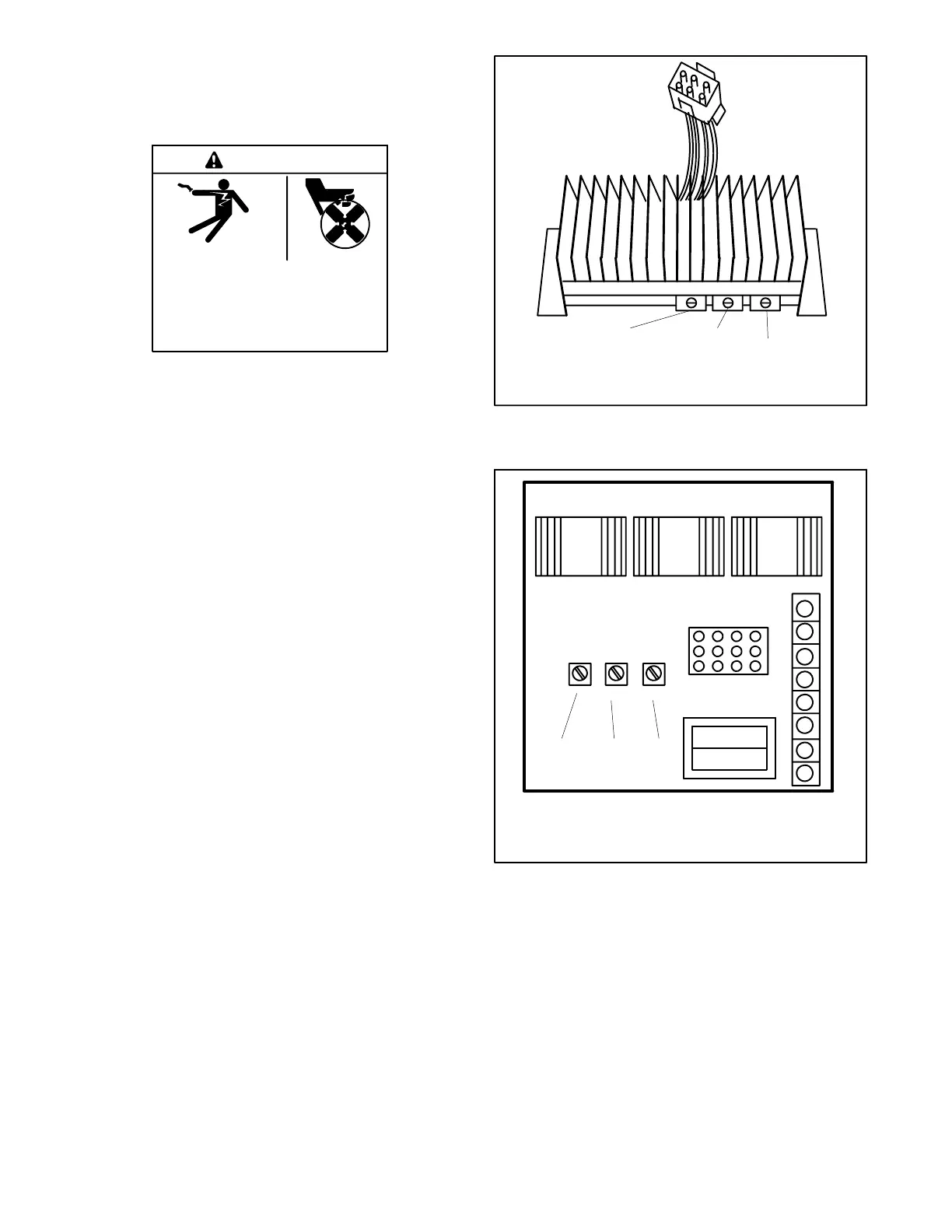
TT-875-11
1
2
3
1. Voltage adjustment potentiometer
2. Stability adjustment potentiometer
3. Volts/Hz adjustment potentiometer
Figure 8-6 PowerBoost™ IIIE Voltage Regulator
(5/7.3E and 4/6EF Models)
8
7
6
5
4
3
2
1
VOLTSV/HZ
STAB
TT-875-11
2
3
1
1. Voltage adjustment potentiometer
2. Stability adjustment potentiometer
3. Volts/Hz adjustment potentiometer
Figure 8-7 PowerBoost™ V Voltage Regulator
(15/20C and 12.5/16CF Models)
 Loading...
