TP-6774 2/14a56 Section 7 Controller
7.9 Battery Charging Module
The junction box contains a battery charging module to
maintain the engine starting battery. The battery
charging module monitors the battery voltage and
provides 10 amps to charge the battery and up to
14.2±2%VDC when the generator set is r unning.
Note: The battery charging module is reverse-polarity
protected.
Before testing the battery charging module, ensure that
no other DC loads are on the generator set. At startup,
after approx. 1 min., check for a change in voltage. If
voltage increases, the battery charging module is
functioning. If voltage decreases, the battery charging
module is inoperative.
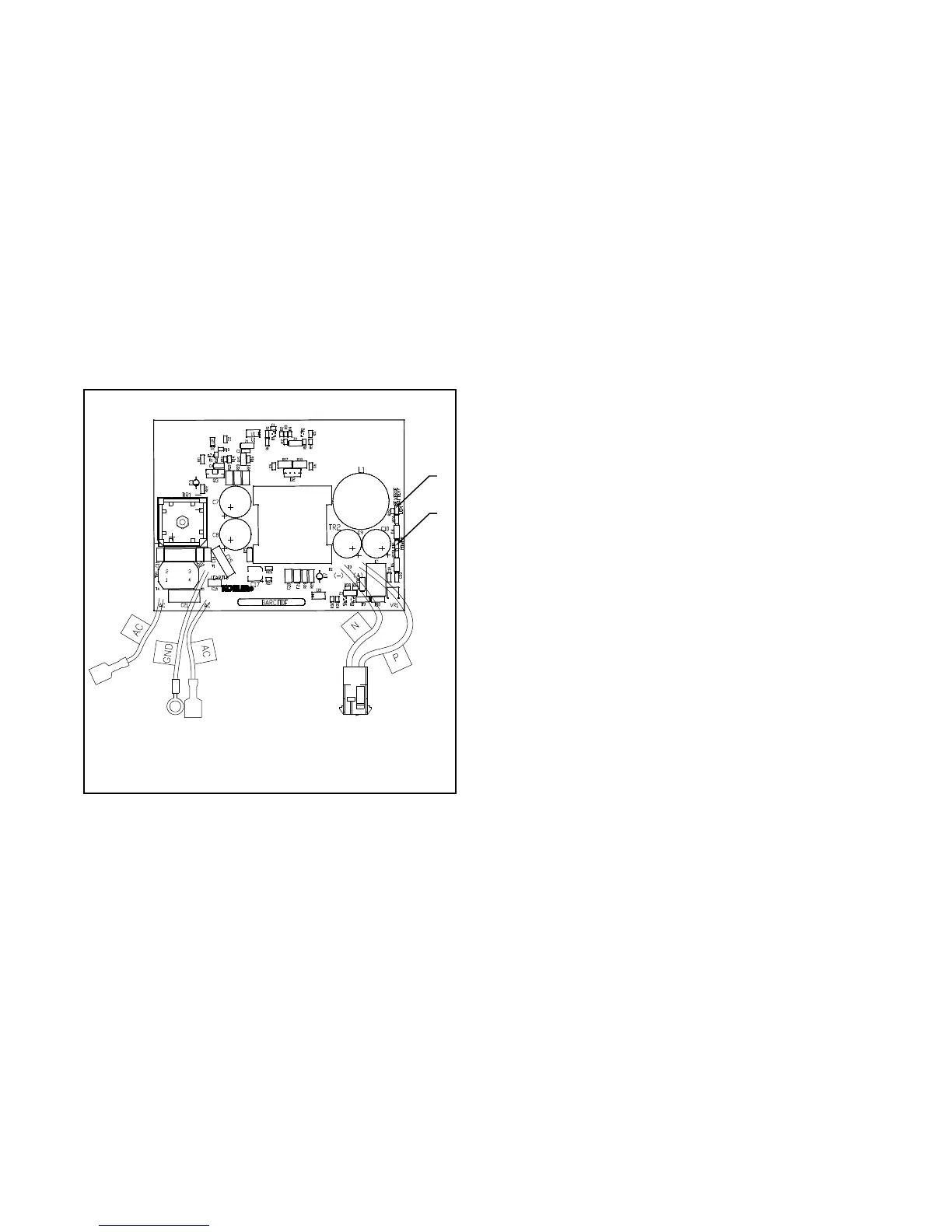
1
GM82844-D
1. LED1 (red), reverse battery
2. LED2 (green), power
2
Figure 7-13 Battery Charging Module
7.10 Controller Logic Specifications
Refer to Figure 7-14 for inhibit and time delays on fault
shutdowns. Refer to Figure 7-15 for inhibit and time
delays on warnings.
Inhibit Time Delay. The inhibit time delay is the time
period following crank disconnect during which the
generator set stabilizes and the controller does not
detect a fault or status event. The inhibit time delay is
not adjustable.
Time Delay (Shutdown or Warning). The time delay
follows the inhibit time delay. The time delay is the time
period between when the controller first detects a fault or
status event and the controller warning or shutdown
lamp illuminates. The time delay is not adjustable.
7.10.1 Fault Shutdown and Warning
Specifications
The following list contains fault shutdown and warning
specifications with time delays.
 Loading...


