TP-6774 2/14a 91Section 9 Generator Disassembly/Reassembly
Section 9 Generator Disassembly/Reassembly
9.1 Disassembly
Disconnect all of the external connections—battery
cables at the battery (negative (--) lead first), AC-output
leads, remote interface connector, water line at the
seawater pump, fuel line at the fuel pump filter inlet, and
exhaust line at the mixing elbow. Remove the sound
shield enclosure, if equipped. Observe all of the safety
precautions listed at the beginning of this manual during
the disassembly/reassembly procedures.
Note: Because this manual covers several models, the
procedure for disassembly may vary because of
product updates and the assembly variations.
Note: Mark leads that are disconnected. Refer to the
wiring diagrams in Section 10 during reassembly.
Disassembly Procedure:
1. Press the start/stop button to stop the generator
set.
2. Press the power button to turn the controller off.
3. Disconnect power to the battery charger, if
equipped.
4. Disconnect the generator set engine starting
battery, negative (--) lead first.
Accidental starting.
Can cause severe injury or death.
Disconnect the battery cables before
working on the generator set.
Remove the negative (--) lead first
when disconnecting the battery.
Reconnect the negative (--) lead last
when reconnecting the battery.
WARNING
Sound Shield Equipped Models: For access to the
generator set to perform regular maintenance, remove
the sound shield doors and roof.
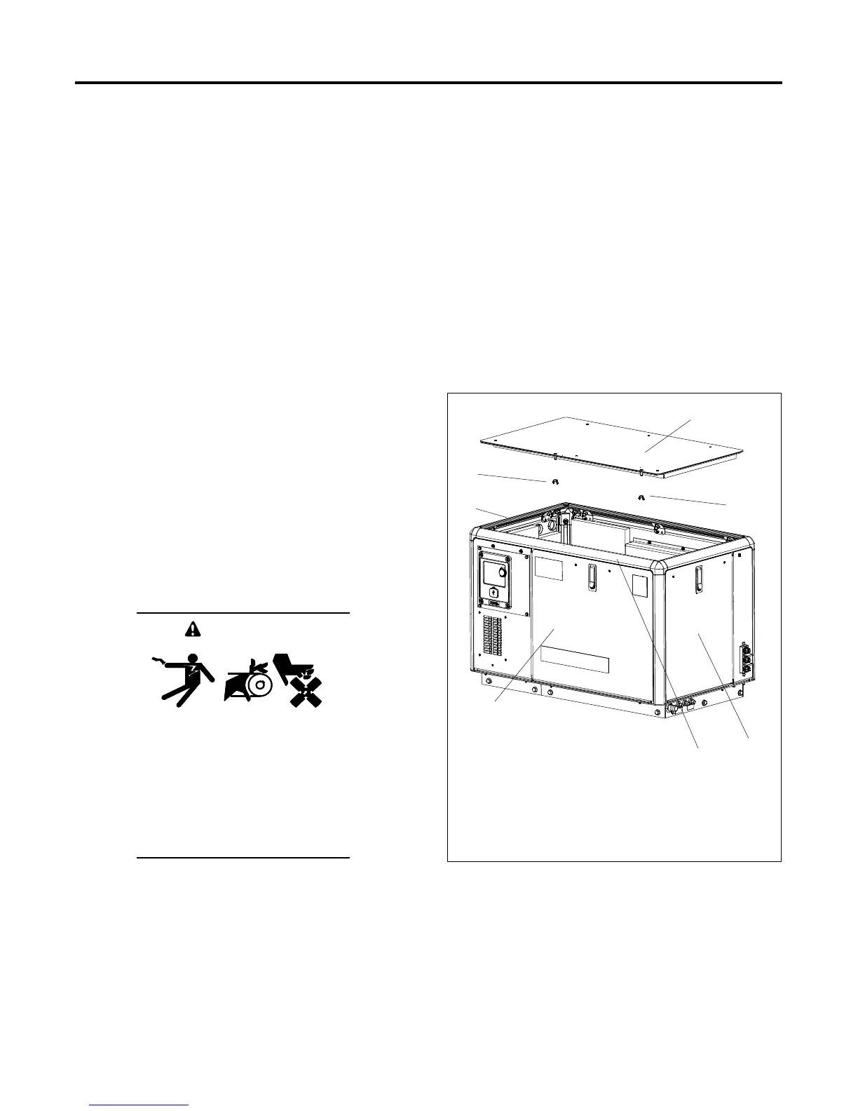
5. Sound-Shielded Models: Open the service-side
door.
6. Sound-Shielded Models: Release the two wing
nuts located underneath the roof. See Figure 9-1.
7. Sound-Shielded Models: Lift up the roof.
8. Sound-Shielded Models: Slide the roof towards
the service side of the unit for removal.
9. Sound-Shielded Models: Open the front, rear,
and non-service side doors as needed.
1
1. Sound shield roof
2. Wing nut
3. Alternator-end door
4. Service-side door
5. Front rail
6. Engine-end door
2
2
4
3
5
6
Figure 9-1 Sound Shield Roof Removal
 Loading...


