TP-6053 7/04 15Section 4 Fuel System
6
5
4
TP-5586-3
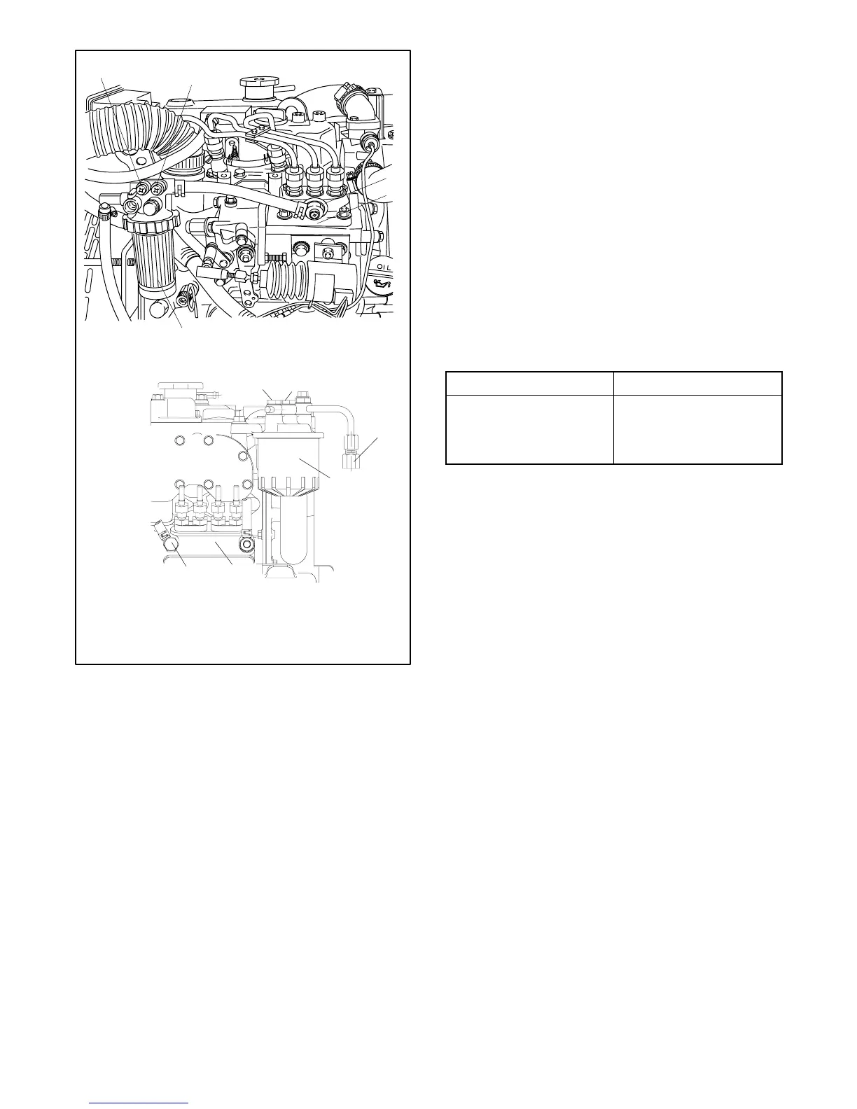
9/10EOZ and 8/9EFOZ Models
5/8EOZ and 4/6.5EFOZ Models
1
2
1
2
4
5
6
3
1. Vent screw, position 1
2. Vent screw, position 2
3. Fuel return
4. Fuel filter
5. Fuel injection pump
6. Vent screw, position 5
Figure 4-4 Fuel System Bleed Points, Typical
4.5 Fuel Solenoid
The fuel solenoid serves to pull the injector pump lever
to the fuel-on position when energized. The fuel
solenoid is spring loaded to return the injector-pump
lever to the fuel-off position when deenergized.
The generators in this manual use a 3-lead fuel
solenoid. This solenoid has a white lead (P) which
energizes the pull-in coil only during cranking. During
operation, the red lead energizes the hold coil and the
black lead is the common ground.
Current (amps) and resistance readings are shown in
Figure 4-5. Resistance readings determine if the
solenoid windings are open or shorted. These readings
must be taken with fuel solenoid disconnected from
engine wiring harness.
Fuel Solenoid Reading
Pull-In
Hold
Black-White (P) Leads
Black-Red Leads
50 Amps
1.0 Amps
0.12--0.26 Ohms
11-13 Ohms
Figure 4-5 Fuel Solenoid Readings
 Loading...

