TP-6053 7/0428 Section 6 Controller Troubleshooting
6.5 Troubleshooting
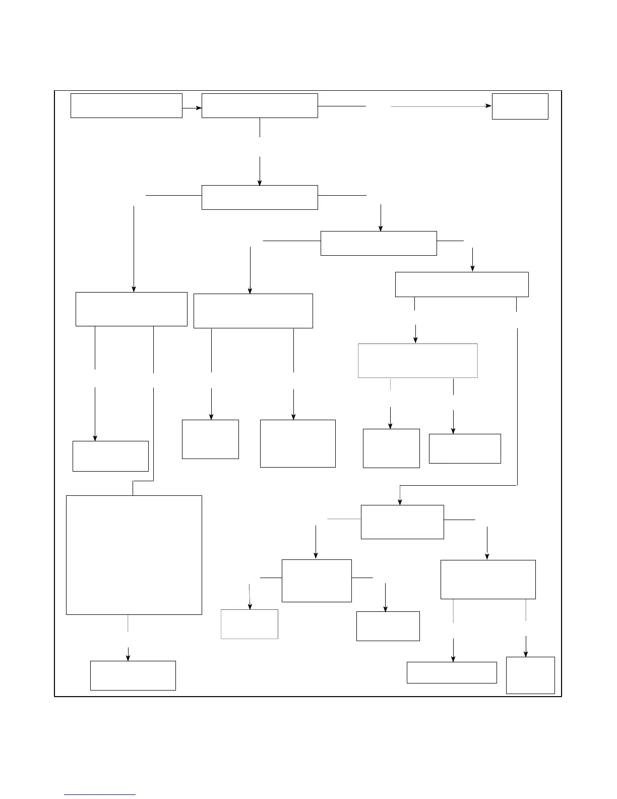
Use the following flow chart as an aid in troubleshooting
the main circuit board and the entire generator set. If the
prescribed remedy does not correct the problem, the
circuit board may have to be replaced.
Is the 10-amp controller
circuit breaker okay?
Reset the
circuit breaker.
Press the start switch
(local or remote).
Does the engine crank?
Yes
No
Is the K2 relay LED lit?
YesNo
Is the K3 relay LED lit?
Yes
No
YesNo
S Check the condition/
connections of the
start/stop switch
(N, 43, and 47).
S Check the battery
condition and
connections.
S Check the connections
at P1--14.
S Do all check okay?
Is the K2 relay
functioning correctly?
No
Yes
Replace
the circuit
board.
The K3 relay or
K1relayisfaulty.
Replace the
circuit board.
Is voltage present
at the S relay coil?
Yes
Is the K20 relay
functioning
correctly?
Is voltage present at
the S relay contact
(starter motor side)?
No
Yes
Replace the S relay.
Replace
the starter
motor.
Go to A
(next page).
Replace the
K20 relay.
Check P4--22
Connection.
Is voltage present at
the K20 relay coil?
Yes
Is the K3 relay
functioning correctly?
No
Replace
the circuit
board.
No
Yes
Check the P1--4
connection.
No
YesNo
Yes
Replace the circuit
board (D9 open).
Figure 6-4 Troubleshooting Relay Controller Circuit Board (1 of 4)
 Loading...

