TP-6053 7/04 25Section 6 Controller Troubleshooting
Section 6 Controller Troubleshooting
6.1 General
The following section covers the controller
troubleshooting procedure for generator sets equipped
with the relay controller and related engine components.
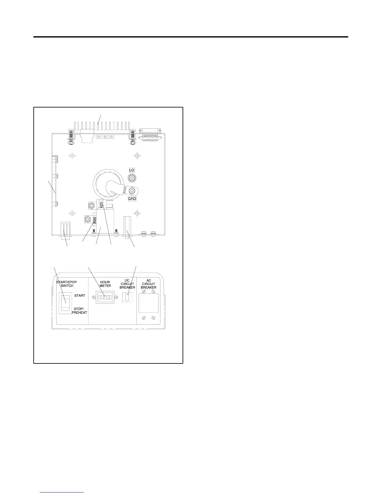
Refer to Figure 6-1 to identify the controller
components.
A-229301-N
1
2
3
4
5
6
2
46
7
1. Voltage regulator
2. DC circuit breaker
3. K25 relay
4. Hourmeter
5. K20 relay
6. START/STOP switch
7. Controller circuit board
Figure 6-1 Controller Internal Components
6.2 Controller Sequence of
Operation
The following text covers the controller’s sequence of
operation during generator start, run, stop, and fault
shutdown modes. Use this as a starting point for
controller fault identification. Use the LEDs on the
controller circuit board to assist in the troubleshooting
process. An illuminated LED indicates that the
respective relay is receiving power; the LED does not
indicate whether that relay is energized. Additional
relay test procedures are covered later in this section.
Refer to the wiring diagrams in Section 10, Voltage
Reconnection and Wiring Diagrams, to assist in the
troubleshooting procedure.
6.2.1 Start
Close the start/stop switch between N (ground) and 47
(local or remote starting).
The K2 relay energizes. The normally open K2 contacts
close to energize the K3 relay (LED3 lights), the K25
(fuel solenoid) relay, the controller hourmeter, and the
generator armature exciter field.
The K25 relay normally open contacts close to energize
the fuel solenoid.
The K3 relay normally open contacts close to energize
the K20 (starter) relay. The K20 relay normally open
contacts close to energize the S relay (starter solenoid).
The S relay normally open contacts close to energize
the starter motor.
6.2.2 Run
The B1 and B2 windings of the stator supply AC voltage
to the bridged rectifier (BR1), the K1 relay energizes
(LED1 lights). After a 5--10 second time delay, the K5
relay energizes (LED5 lights).
Note: Voltage to the K1 and K5 relays is rectified and
regulated at 12 volts DC by the bridge rectifier
(BR1) and the voltage regulator (VR1).
Stator winding 33--34 provides a voltage sensing source
to the voltage regulator (PBIIIE).
The normally open K1 contacts close to maintain
voltage to the K2 relay (LED2 remains lit).
The normally open K2 contacts remain closed to
maintain voltage to the fuel solenoid and the controller
hourmeter.
 Loading...

