Section 4
Troubleshooting
4-l. GENERAL
CAUTION
When troubleshooting a generator set, always consider the
simplest causes first. Narrow the problem down to a func-
tional system, such as fuel or ignition. To operate efficient-
ly, an engine must have sufficient fuel, a good ignition
spark and good compression. All adjustments must be
correct. For a generator to produce the required electricity,
all parts must be clean, all connections tight, and all com-
ponents in working order. See Table 4-l for Engine Trou-
bleshooting and Table 4-2 for Generator Troubleshooting.
4-2. RV SYSTEMS CHECK
The “RV Systems Check” is designed to check the electri-
cal status of an RV generator set prior to connecting and
testing with the controller. If the generator does not check
out in each step, correct the malfunction before proceeding
to the next step.
Do not push the V.B.U. button after the “GEN
ON” lamp is on. Voltage regulator damage may
resu It.
CAUTION
Do not use the RV Systems Check as a replace-
ment for the controller. The hi-temp and low
oil pressure switches will not shut the machine
down in the event of a malfunction. Generator
damage will result.
1. Make sure the battery is properly connected and oil is
at proper level.
CAUTION
Do not push the CRANK button after the en-
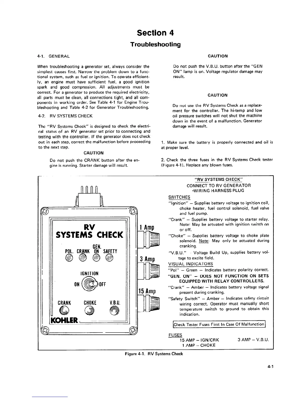
2. Check the three fuses in the RV Systems Check tester
gine is running. Starter damage will result.
(Figure 4-l). Replace any blown fuses.
RV
‘II I
SYSTEMS CHECK
GEN
POL. CRANK ON’ SAFETY
IGNITION
ON OFF
CRANK CHOKE
V. B.U.
“RV SYSTEMS CHECK”
CONNECT TO RV GENERATOR
*WIRING HARNESS PLUG
SWITCHES
“Ignition” -
Supplies battery voltage to ignition coil,
choke heater, fuel control solenoid, fuel valve
and fuel pump.
“Crank” -
Supplies battery voltage to starter relay.
Note: May be actuated with ignition switch on
or off.
“Choke” - Supplies battery voltage to choke plate
solenoid. Note: May only be actuated during
cranking.
“V.B.U.” -
Voltage Build Up, supplies battery vol-
tage to excite field.
VISUAL INDICATORS
“Pol” - Green -
Indicates battery polarity correct.
“GEN. ON” -. DOES NOT FUNCTION ON SETS
EQUIPPED WITH RELAY CONTROLLERS.
“Crank” - Amber -’
Indicates battery voltage signal
present during cranking.
“Safety Switch” - Amber - Indicates safety circuit
wiring correct. Operator must manually short
temperature switch to ground to obtain this
indication.
[Check Tester Fuses First In Case Of Malfunction 1
FUSES
15 AMP - IGN/CRK
1 AMP -CHOKE
3 AMP - V.B.U.
Figure 4-1. RV Systems Check
4-1
 Loading...
