2. Connect brush leads in series with 12-Volt battery and
DC ammeter as shown in Figure 6-37.
3. Ammeter reading should approximate battery voltage
divided by specified rotor resistance (Table 6-1).
4. Record ammeter reading.
5. Start generator set and run at NO load.
6. Observe ammeter with unit running. If current increases
considerably, a running short in the rotor has been detected.
EXCITER /
VOLTAGE r 1
REGULATOR ,-‘&I;
DC
BATTERY
SLIP RINGS J BRUSHES
Figure 6-37. Separate Excitation Connections
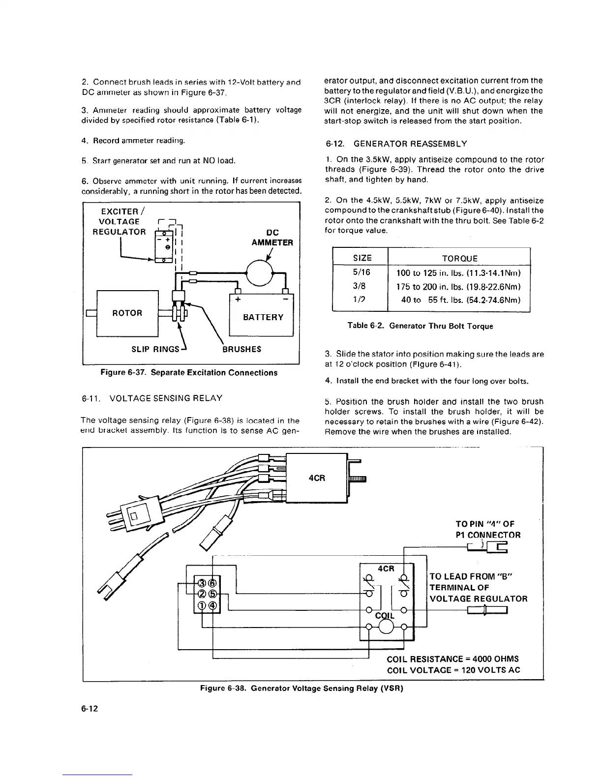
6-l 1. VOLTAGE SENSING RELAY
erator output, and disconnect excitation current from the
battery to the regulator and field (V.B.U.), and energize the
3CR (interlock relay). If there is no AC output; the relay
will not energize, and the unit will shut down when the
start-stop switch is released from the start position.
6-12. GENERATOR REASSEMBLY
1. On the 3.5kW, apply antiseize compound to the rotor
threads (Figure 6-39). Thread the rotor onto the drive
shaft, and tighten by hand.
2. On the 4SkW, 55kW, 7kW or 7.5kW, apply antiseize
compound to the crankshaft stub (Figure 6-40). Install the
rotor onto the crankshaft with the thru bolt. See Table 6-2
for torque value.
I
SIZE
I
TORQUE
I
5116
3/8
l/2
100 to 125 in. Ibs. (11.3-14.1Nm)
175 to 200 in. Ibs. (19.8-22.6Nm)
40 to 55 ft. Ibs. (54.2-74.6Nm)
Table 6-2. Generator Thru Bolt Torque
3. Slide the stator into position making sure the leads are
at 12 o’clock position (Figure 6-41).
4. Install the end bracket with the four long over bolts.
5. Position the brush holder and install the two brush
holder screws. To install the brush holder, it will be
The voltage sensing relay (Figure 6-38) is located in the
necessary to retain the brushes with a wire (Figure 6-42).
end bracket assembly. Its function is to sense AC gen-
Remove the wire when the brushes are installed.
’ TO PIN “4” OF
PI CONNECTOR
TO LEAD FROM “B”
TERMINAL OF
VOLTAGE REGULATOR
I
I
COIL RESISTANCE = 4000 OHMS
COIL VOLTAGE = 120 VOLTS AC
Figure 6-38. Generator Voltage Sensing Relay (VSR)
6-12
 Loading...
