5. When installing the oil tank, make sure O-rings are not
damaged. Apply grease to the O-rings, fitting and the oil
tank bore. Push tank on squarely.
6-3.2 On the 7.5kW generator set, if the rotor seems loose
but cannot be removed, the flywheel has become free of
the crankshaft taper. To separate rotor from flywheel,
adapter, and stub shaft proceed as follows.
I. Remove eight bolts fastening generator adapter to bell
housing (Figure 6-24).
2. Pull rotor, adapter, and flywheel away from engine.
3. Slide adapter over generator fan as far as possible.
4. Remove four bolts fastening stub shaft to flywheel
(Figure 6-25).
Figure 6-24. Adapter Removal
Stub
Flywheel
Figure 6-25. Separating Stub Shaft and Flywheel
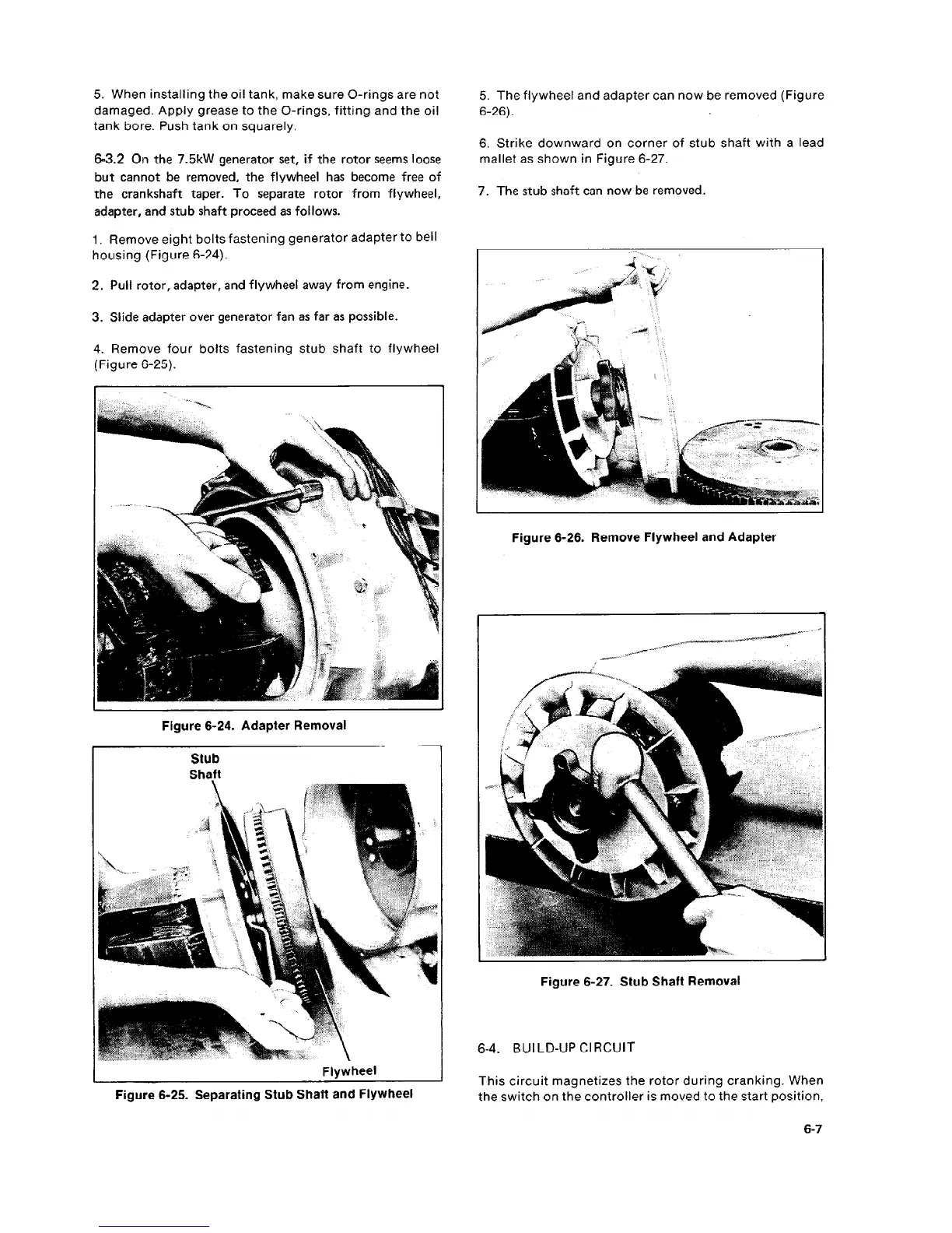
5. The flywheel and adapter can now be removed (Figure
6-26).
6. Strike downward on corner of stub shaft with a lead
mallet as shown in Figure 6-27.
7. The stub shaft can now be removed.
- .
Figure 6-26. Remove Flywheel and Adapter
Figure 6-27. Stub Shaft Removal
6-4. BUI LD-UP Cl RCUIT
This circuit magnetizes the rotor during cranking. When
the switch on the controller is moved to the start position,
6-7
 Loading...
