TP-5631 7/96 Specifications 1-7
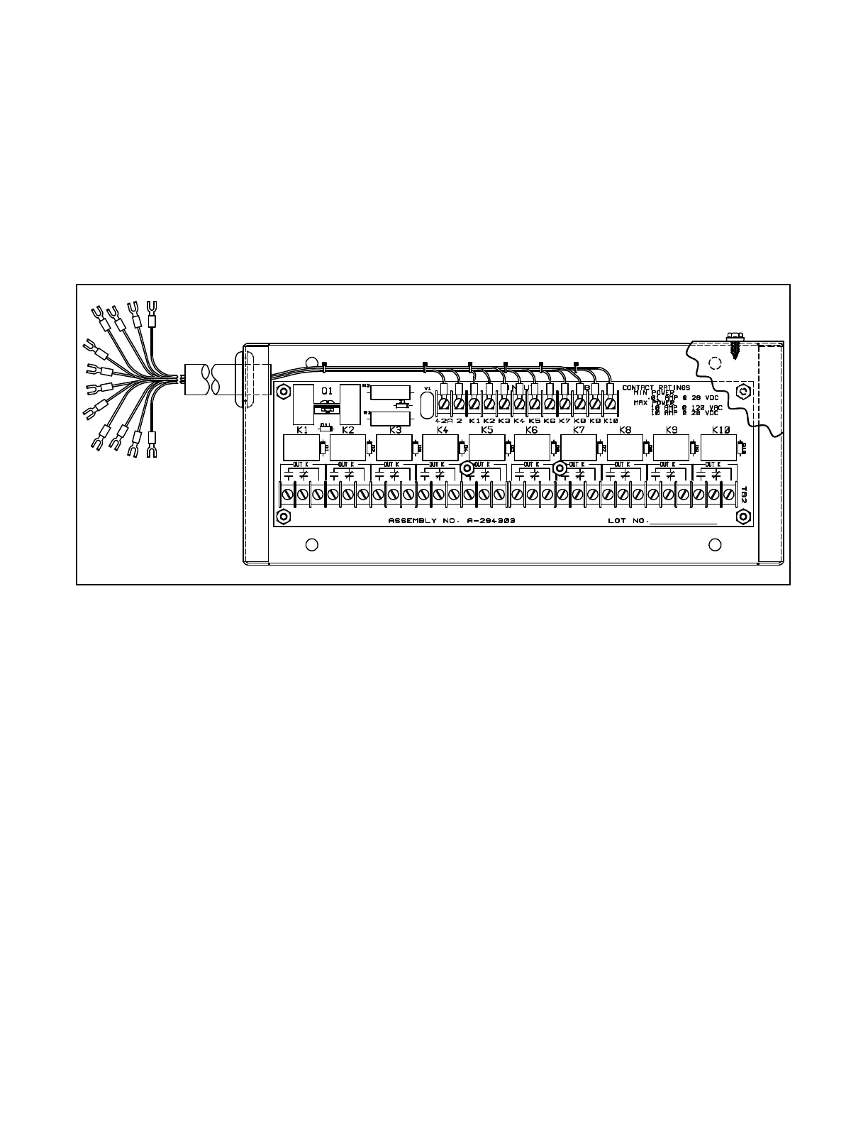
Ten-Relay Dry Contact Kit
(microprocessor controller)
The ten-relay dry contact kit allows monitoring of the
standby system and/or the ability to activate
accessories such as derangement panels. The kit
includes ten sets of relay contacts for connection of
customer provided devices to generator set functions.
Connect warning devices (lamps, audible alarms) and
other accessories to the controller outputs listed.
Connectatotalofthreedrycontact kits to thecontroller.
AninternalviewofthecontactkitisshowninFigure 1-8.
Typical Contact Kit Output Connections:
Overspeed
Overcrank
Low Oil Pressure
Auxiliary Fault
Emergency Stop
A-273936
Figure 1-8. Ten-Relay Dry Contact Kit
Accessory Connection
(microprocessor controller)
The Decision-Makerä 3 controller circuit board is
equipped with a terminal strip (TB1) for easy connection
of generator set accessories. Do not direct connect
accessories to the controller terminal strip. Connect all
accessories to either a single-relay dry contact kit or to a
ten-relay dry contact kit. Connect the dry contact kit(s)
to the controller terminal strip. Connect alarms, battery
chargers, remote switches, and other accessories to
the dry contact kit relay(s) using 18 or 20 gauge
stranded wire.
To connect accessories to the controller TB1 terminal
strip, lower the controller circuit board panel until it is
lying flat. Route dry contact relay leads through the
controller port and guide loops to the circuit board
terminal strip. The controller circuit board panel must be
lying flat to ensure adequate slack in dry contact relay
leads and/or harnesses. For specific information on
accessory connections, refer to Figure 1-10, the
accessory wiring diagram and the instruction sheet
accompanying each kit.
 Loading...