5-2 Generator Reconnection TP-5631 7/96
Four-Lead (Single-Phase)
Generator Sets
NOTE
Current transformers (CTs) are used only ongenerator
sets equipped with controllers with meters.
NOTE
Position current transformers CT1, CT2, and CT3 with
dot or HI side toward generator set.
See Figure 5-1 for four-lead reconnectable
(single-phase) generator set options.
60 Hz 50 Hz
100-120 volt X
100-120/200-240 volt X X
200-240 volt X
Figure 5-1. Four-Lead, Single-Phase Generator
Set Voltage Connection Options
NOTE
Microprocessor controller only: Make fine
adjustment ±5% using voltage adjustment
potentiometer on the controller front panel.
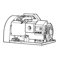
100-120 Volt Configurations
The load side terminals of the circuit breaker are not to
be connected together when a factory two-pole circuit
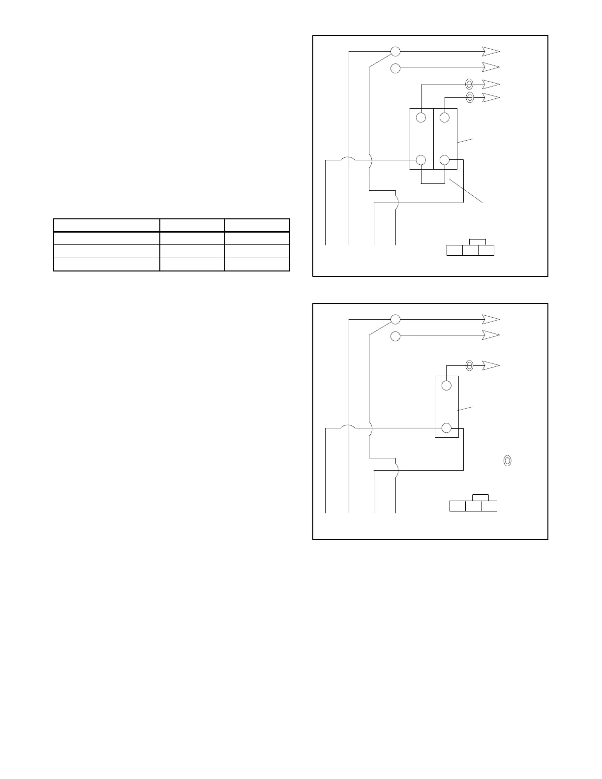
breaker is used, see Figure 5-2. If the installation
requiresa100-120volt,2wiresystem,useasinglepole
circuit breaker. See Figure 5-3. When connecting
stator phase leads together, size output lead (L1)
accordingly. Use a jumper lead on the line side of the
circuit breaker to balance the load of the generator set.
L0-L1
L0-L2
60 Hz
100-120 volt
100-120 volt
50 Hz
100-120 volt
100-120 volt
4 3 2 1
Stator Leads
LO
GRD
LO (Neutral)
Ground
Load
Side
Line
Side
Factory
Two-Pole
or (2) 1-Pole
Circuit
Breakers
Jumper
Lead
L1
L2
TP-5631-5
CT1
CT2
UP V7 LO
TB2
Meter Scale
Lamp Jumper
Figure 5-2. 100-120 volt, 3 wire
4 3 2 1
Stator Leads
LO
GRD
LO (Neutral)
Ground
Load
Side
Line
Side
1-Pole
Circuit
Breaker
L1
TP-5631-5
CT1
CT2 not used
UP V7 LO
TB2
Meter Scale
Lamp Jumper
Figure 5-3. 100-120 volt, 2 wire
 Loading...