1.
Loosen
lock plate mounting bolts (1) and remove lock
plate (2).
Lock plates (2) are at both ends of pin (3).
2.
Pull out pin (3).
3.
Change the position of the pin hole of the shank, and in-
stall pin (3).
4.
Install lock plate (2) with bolts (1).
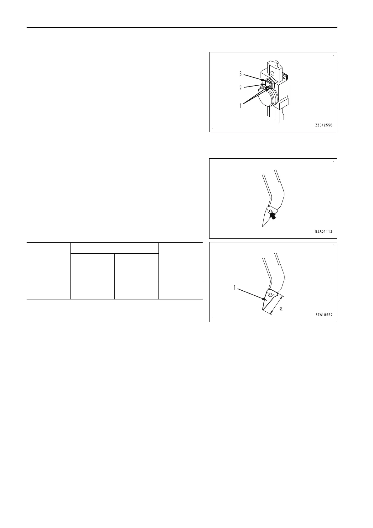
METHOD FOR REPLACING RIPPER POINT
A point is installed to protect the shank. If the point is worn, replace it according to the following procedure.
1.
Put a pin puller to the pin indicated by the arrow, and hit it
with a hammer to drive out the pin.
The pin comes off.
2.
Replace the point.
3.
Insert the pin halfway.
4.
Drive in the pin with the hammer.
Criteria
Remedy
Standard di-
mension
( mm { in} )
Repair limit
( mm { in} )
Wear (a) of rip-
per point (1)
277 {10.9} 170 {6.7} Replace
HANDLE HYDRAULIC RIPPER ATTACHMENTS AND OPTIONS
6-6

 Loading...