SERVICE PROCEDURE MAINTENANCE
4-44
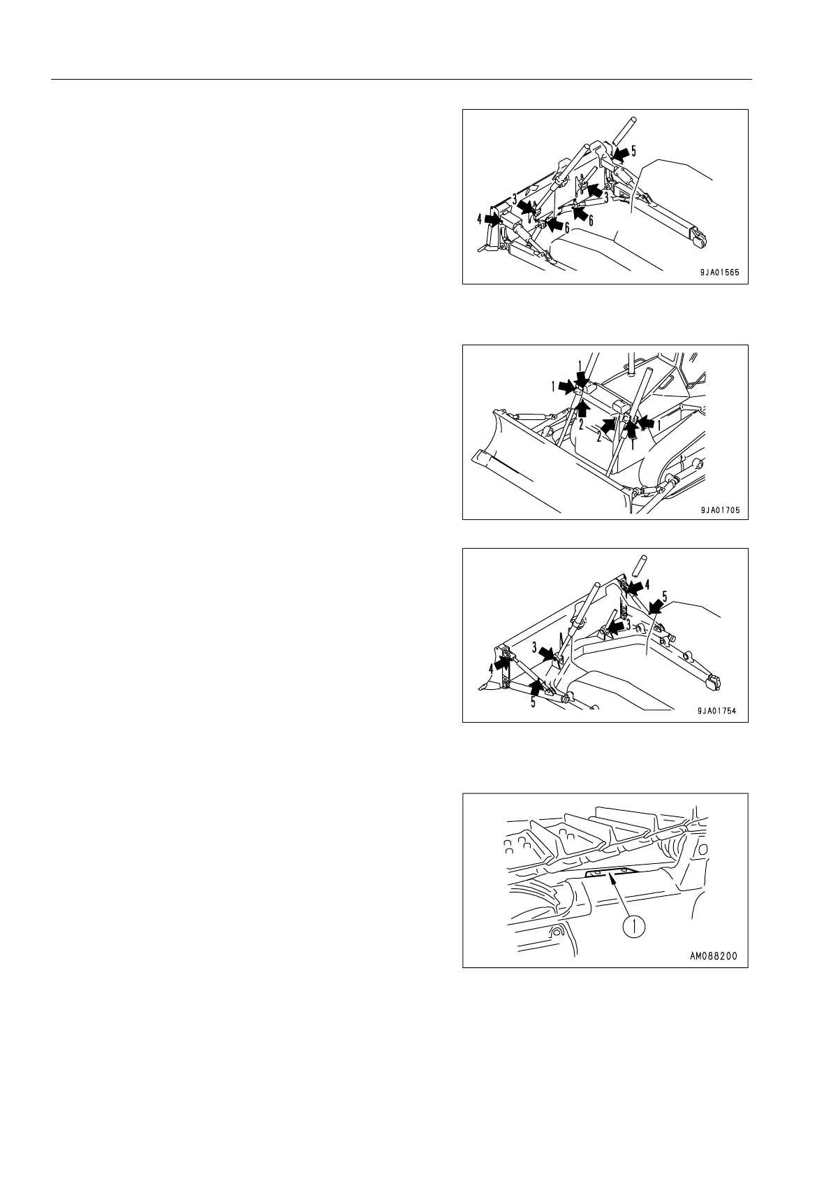
(3) Lift cylinder ball joint (2 places)
(4) Tilt cylinder ball joint (1 place)
(5) Pitch cylinder ball joint (1 place)
(6) Brace ball joint (2 places)
ANGLEDOZER
(1) Lift cylinder support yoke (4 places)
(2) Lift cylinder support shaft (2 places)
(3) Lift cylinder ball joint (2 places)
(4) Tilt brace ball joint (2 places)
(5) Tilt brace thread (2 places)
GREASE EQUALIZER BAR SIDE PIN
Left and right 2 places each
1. Remove all dirt from the top of the track frame and cover
(1).
2. Clean the grease fitting indicated with the arrow, then
supply grease to that fitting with a grease pump.
REMARK
● Supply 3 shots of grease (Operate the grease pump lever
3 times) to each grease fitting, and check that grease is
newly discharged through the seal lip.
● If grease is not newly discharged through the lip, continue
supplying grease until it is discharged.
 Loading...