STRUCTURE AND FUNCTION
60-18 EX20 Series
BRAKE
Wheel brake
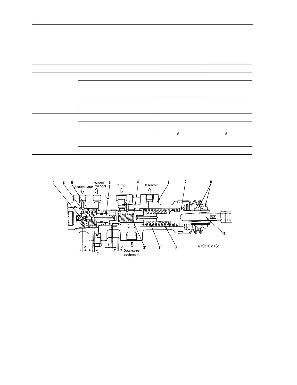
Brake valve
When the brake pedal is operated, the hydraulic oil in the power steering hydraulic circuit is adjusted to a pressure that
matches the amount that the pedal is depressed, and this actuates the wheel cylinder. If the engine stalls and the flow of
oil from the hydraulic pump stops, the pressure stored in the accumulator makes it possible to carry out braking operations
several times.
Model FD100/115 FD135/150E/160E
Brake specifications
Type 2–leading type 2–leading type
Inside diameter of drum 393.7 mm 432 mm
Lining material Non–asbestos Non–asbestos
Lining size (width x thickness) 125 mm × 13.1 mm 125 mm × 12 mm
Inside diameter of wheel cylinder 41.3 mm 47.62 mm
Brake valve
Regulated pressure
12.7 MPa {130 kg/cm
2
}
130 kg/cm
2
Piston stroke 11 mm 11 mm
Inlet flow 25 /min 25 /min
Accumulator
Oil pressure at max. pressure storage
13.7 MPa {140 kg/cm
2
}
140 kg/cm
2
Pressure storage capacity 300 cc 300 cc
1. Body 3”. Spring 7. Ball valve
2. Input piston 4. Spool 8. Nut (for pressure adjustment)
3. Spring 5. Reaction piston 9. Return spring
3’. Spring 6. Valve rod 10. Push rod
BRAKE