TESTING AND ADJUSTING
20-12 EX20 Series
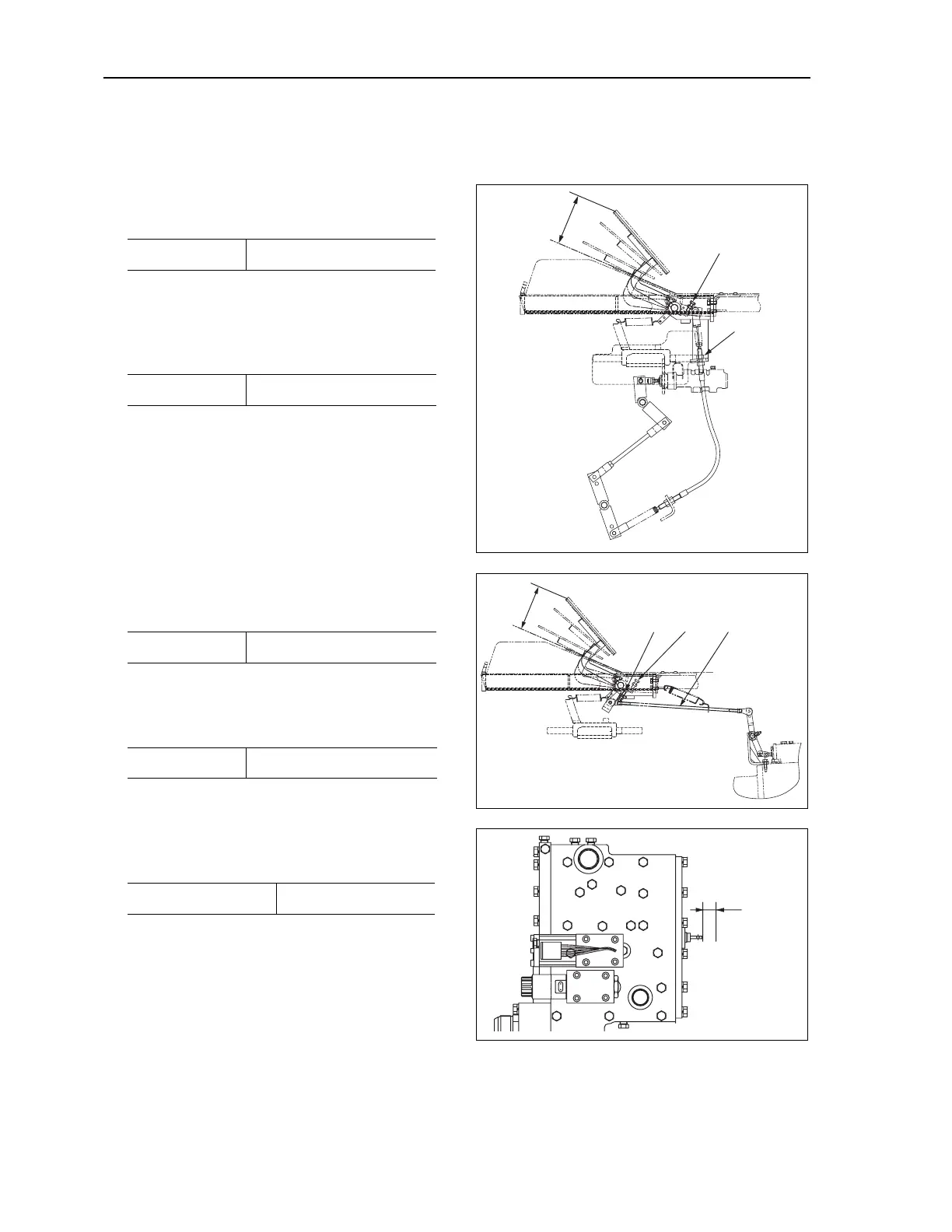
ADJUSTIN BRAKE/INCHING PEDAL
BRAKE PEDAL
1. Pedal height (from floor plate)
Adjust with stopper bolt (1).
2. Valve clearance and pedal play
After adjusting the pedal height, adjust the clearance
of the valve plunger head and bolt with bolt (2).
Valve clearance
INCHING PEDAL
1. Pedal height (from floor plate)
Adj ust with stopper bolt (3).
2. Protrusion of inching spool
After adjusting the pedal height, adjust with linkage
(4).
3. Interconnected travel
Adjust with bolt (5) so that the inching pedal and
brake pedal are interconnected for the travel shown
below when the inching pedal is depressed.
Pedal height (h1) 234 mm (9.21 in)
Pedal play 2–6 mm (0.08–0.24 in)
Pedal height (h2) 234 mm (9.21 in)
Protrusion (a) 20 mm (0.78 in)
Interconnected travel 50 mm (1.97 in)
h1
1
2
h2
53
4
a
ADJUSTIN BRAKE/INCHING PEDAL