FOREWORD HANDLING ELECTRIC AND HYDRAULIC EQUIPMENT
WA320-6 00-21 b
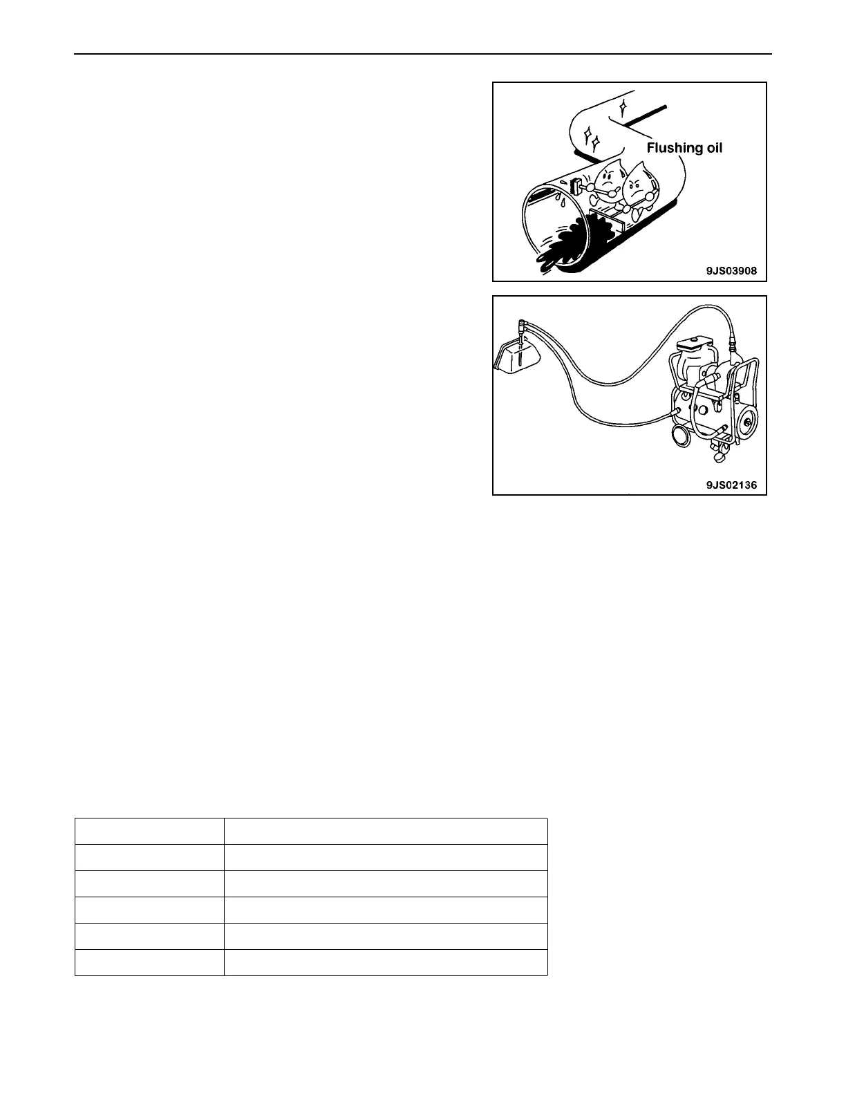
6. Flushing operations
After disassembling and assembling the equipment, or changing
the oil, use flushing oil to remove the contaminants, sludge, and
old oil from the hydraulic circuit. Normally, flushing is carried out
twice: primary flushing is carried out with flushing oil, and
secondary flushing is carried out with the specified hydraulic oil.
7. Cleaning operations
After repairing the hydraulic equipment (pump, control valve, etc.)
or when running the machine, carry out oil cleaning to remove the
sludge or contaminants in the hydraulic oil circuit. The oil cleaning
equipment is used to remove the ultra fine (about 3 mm) particles
that the filter, built in the hydraulic equipment, cannot remove; it is
an extremely effective device.
Handling Connectors Used for Engines 00
The following engines use the connectors described in this section.
• 95E-5
• 107E-1
• 114E-3
• 125E-5
• 140E-5
• 170E-5
• 12V140E-3
★ Your machine has a 107E-1 diesel engine.
Slide Lock Type 00
FRAMATOME-3, FRAMATOME-2
★ 95 – 170, 12V140 engines
• Pressure sensors and NE speed sensor
Engine Sensor
125, 170, 12V140 Intake air pressure sensor in intake manifold: PIM
125, 170, 12V140 Oil pressure sensor: POIL
95, 107, 114 Oil pressure switch
95 – 170, 12V140 Ne speed sensor of flywheel housing: NE
125, 170, 12V140 Ambient pressure sensor: PAMB
 Loading...