FOREWORD HANDLING ELECTRIC AND HYDRAULIC EQUIPMENT
00-22 b WA320-6
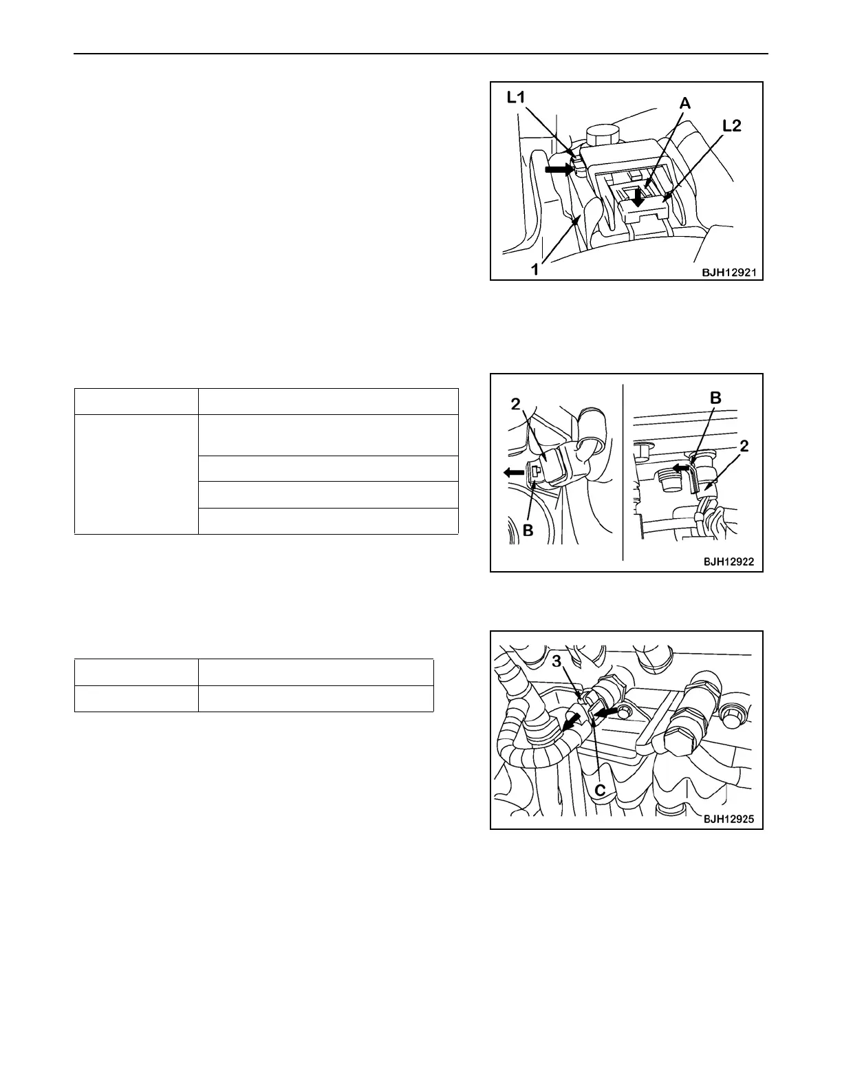
Unplug connector (1) according to the following procedure.
1. Slide lock (L1) to the right.
2. While pressing lock (L2), pull out connector (1) toward you.
3. Even if lock (L2) is pressed, connector (1) cannot be pulled toward
you if part A does not float. In this case, float part A with a small
screwdriver while pressing lock (L2), and then pull out
connector (1) toward you.
Pull Lock Type 00
PACKARD-2
★ 95 – 170, 12V140 engines
• Temperature sensors
• Unplug the connector by pulling lock (B) (on the wiring harness
side) of connector (2) outward.
Push Lock Type 00
★ 95, 107, 114 engines
Unplug connector (3) according to the following procedure.
1. While pressing lock (C), pull out connector (3) in the direction of
the arrow.
★ 114 engine (see graphic)
Engine Sensor
95 – 170, 12V140
Intake air temperature sensor in intake
manifold: TIM
Fuel temperature sensor: TFUEL
Oil temperature sensor: TOIL
Coolant temperature sensor: TWTR, etc.
Connector Sensor
BOSCH0-03 Fuel pressure sensor in common rail

 Loading...