Connecting the 713 and 714
5.2 Wiring the CAT 5 LINE IN/LINE OUT RJ-45 Connectors
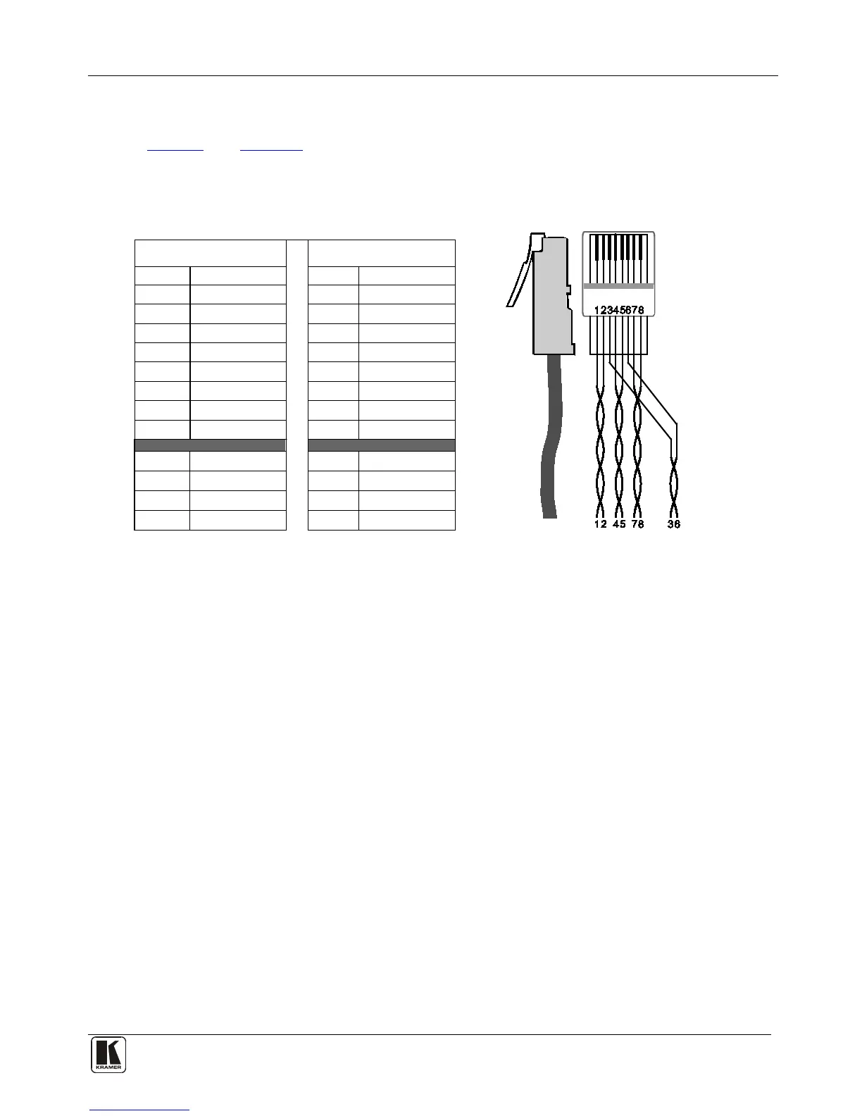
Table 3 and Figure 6 define the CAT 5 pinout, using a straight pin-to-pin cable
with RJ-45 connectors. When using STP cable, connect/solder the cable shield to
the connector shield.
EIA /TIA 568A EIA /TIA 568B
1 Green / White 1 Orange / White
2 Green 2 Orange
3 Orange / White 3 Green / White
4 Blue 4 Blue
5 Blue / White 5 Blue / White
6 Orange 6 Green
7 Brown / White 7 Brown / White
8 Brown 8 Brown
Pair 1 4 and 5 Pair 1 4 and 5
Pair 2 3 and 6 Pair 2 1 and 2
Pair 3 1 and 2 Pair 3 3 and 6
Pair 4 7 and 8 Pair 4 7 and 8
 Loading...