4 Defining the 713/714 Video-Audio Line Transmitter/Receiver
This section defines the:
• 713 Video-Audio Line Transmitter (see Section
4.1)
• 714 Video-Audio Line Receiver (see Section
4.2)
4.1 Defining the 713 Video-Audio Line Transmitter
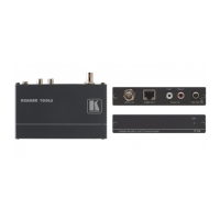
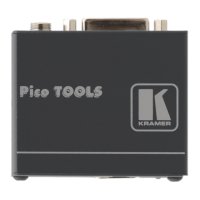
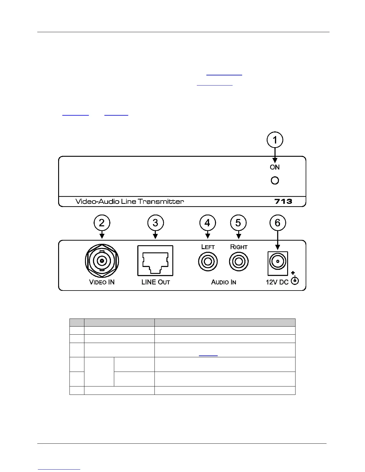
Figure 1 and Table 1 define the front and rear panels of the 713 Video-Audio Line
Transmitter.
Figure 1: 713 Video-Audio Line Transmitter Front and Rear Panels
Table 1: 713 Video-Audio Line Transmitter Front and Rear Panel Features
# Feature Function
1 ON LED Lights green when the unit is powered on
2 VIDEO IN BNC Connector Connect to the composite video source
3 LINE OUT RJ-45 Connector
Connect to the LINE IN RJ-45 connector on the 714 using
CAT 5 cable (see
Figure 2)
4
AUDIO IN
LEFT RCA
Connector
Connect to the left channel of the unbalanced stereo audio
source
5 RIGHT RCA
Connector
Connect to the right channel of the unbalanced stereo
audio source
6 12V DC Connector Connect to the supplied power adapter, center pin positive
 Loading...