5.4 Controlling the TP-582T via the REMOTE Terminal Block
Connector
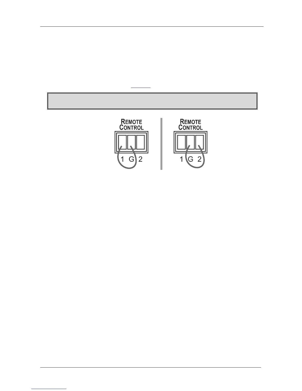
The contact closure remote control pins operate in a similar way to the
INPUT SELECT button. Using the contact closure remote control you can
select the HDMI input. To do so, momentarily connect the required input
pin (IN 1 or IN2) on the REMOTE CONTROL terminal block connector to
the GND (Ground) pin, as Figure 7 illustrates.
Do not connect more than one PIN to the GND PIN at the same time.
Figure 7: Connecting the Contact Closure Remote Control PINs
5.5 Connecting to a PC
You can connect to the transmitter/receiver system via an RS-232
connection using, for example, a PC. Note that a null-modem
adapter/connection is not required.
To connect via RS-232, connect the RS-232 9-pin D-sub rear panel port on
the transmitter/receiver system unit via a 9-wire straight cable (pin 2 to pin
2, pin 3 to pin 3, pin 5 to pin 5) to the RS-232 9-pin D-sub port on your PC.
 Loading...