11 SERVICE WORK ON THE CHASSIS 49
S01227-10
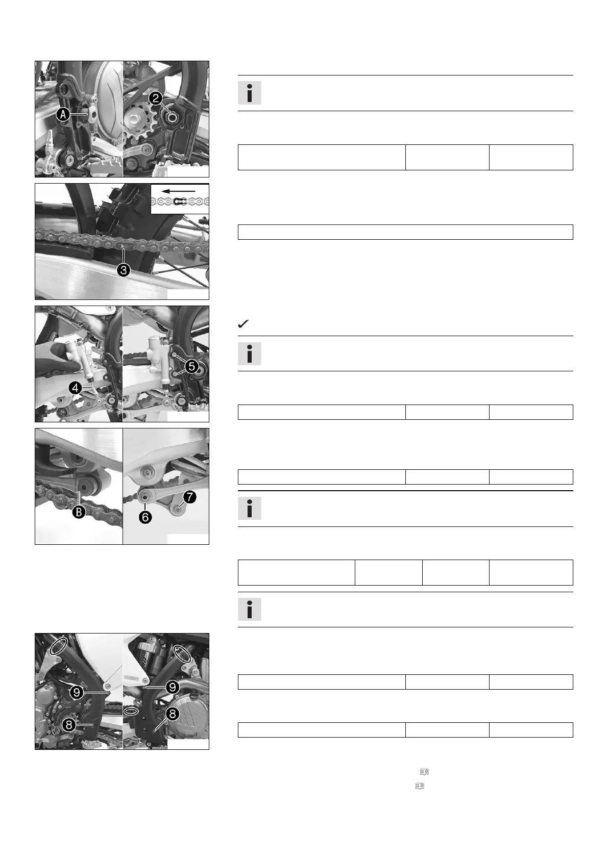
– Position the swingarm and mount the swingarm pivot.
Info
Pay attention to flat area
A
.
–
Mount and tighten nut
2
.
Guideline
Nut, swingarm pivot M16x1.5 100 Nm
(73.8 lbf ft)
S01222-11
– Mount the chain.
–
Connect the chain with connecting link
3
.
Guideline
The closed side of the chain joint lock must face in the direction of travel.
S01228-10
– Position the foot brake cylinder.
Push rod
4
engages in the foot brake cylinder.
Info
Ensure that the dust boot is correctly seated.
–
Mount and tighten screws
5
.
Guideline
Remaining screws, chassis M6 10 Nm (7.4 lbf ft)
S01229-10
– Position the angle lever and linkage lever.
–
Mount and tighten fitting
6
.
Guideline
Nut, linkage lever to angle lever M14x1.5 80 Nm (59 lbf ft)
Info
Pay attention to flat area
B
.
–
Mount and tighten screw
7
.
Guideline
Screw, bottom shock
absorber
M10 60 Nm
(44.3 lbf ft)
Loctite
®
2701™
Info
Raise the wheel slightly to be able to mount the screw more easily.
S01219-11
– Position the frame protectors on the left and right.
–
Mount and tighten screws
8
with the washers.
Guideline
Screw, frame protector M5 3 Nm (2.2 lbf ft)
–
Mount and tighten screws
9
.
Guideline
Screw, frame protector M5 3 Nm (2.2 lbf ft)
– Mount the new cable ties.
Finishing work
– Check the free travel of the foot brake lever. ( p. 71)
– Remove the motorcycle from the lift stand. ( p. 40)
 Loading...