17 TUNING THE ENGINE
135
–
Turn idle air adjusting screw
1
slowly in a clockwise direc-
tion until the idle speed begins to fall.
– Note the position and turn the idle air adjusting screw slowly
counterclockwise until the idle speed again begins to fall.
– Adjust to the point between these two positions with the high-
est idle speed.
Info
If there is a big engine speed rise, reduce the idle
speed to a normal level and repeat the above steps.
If the procedure described here does not lead to sat-
isfactory results, the cause may be a wrongly dimen-
sioned idling jet.
If you can turn the idle air adjusting screw to the end
without any change of engine speed, mount a smaller
idling jet.
After changing the jet, start from the beginning with
the adjusting steps.
Following extreme air temperature or altitude changes,
adjust the idle speed again.
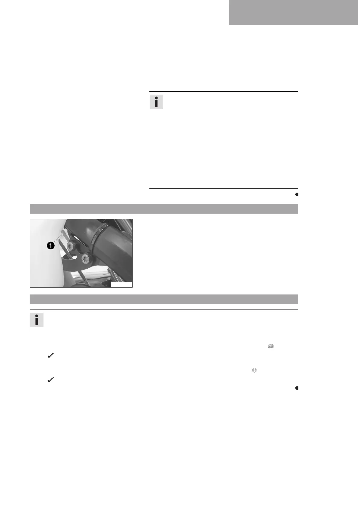
17.6 Ignition curve plug-in connector
F01061-10
Plug-in connector
1
of the ignition timing map adjustment is
located on the frame under the fuel tank.
Possible states
• Soft – The plug-in connector of the ignition timing map
adjustment is disconnected to achieve better rideability.
• Performance – The plug-in connector of the ignition timing
map adjustment is joined to achieve higher performance.
17.7 Changing the ignition timing map
Info
If the map switch (optional) is installed, the ignition timing map can be changed from the handlebar.
Switching the ignition timing map from Performance to Soft
–
Disconnect plug-in connector
1
of the ignition timing map adjustment. (Figure F01061-10 p. 135)
Soft – better rideability
Switching the ignition timing map from Soft to Performance
–
Join plug-in connector
1
of the ignition timing map adjustment. (Figure F01061-10 p. 135)
Performance – better performance

 Loading...