Section 1: Assembly & Set-up
Table of Contents
AP-SC7072 Skid Cutter 326-974MK 2/6/19
12
Pressure Gauge Assembly
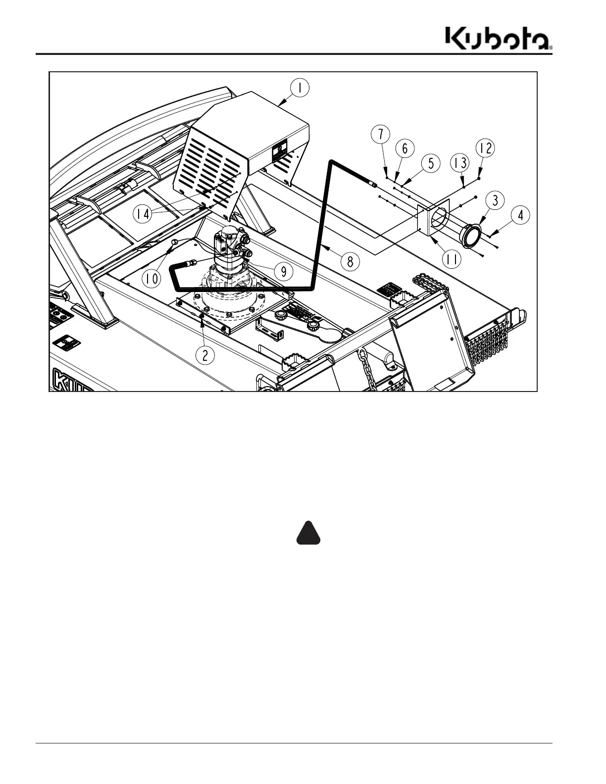
Figure 1-7
70407
Pressure Gauge Assembly (Optional)
Refer to Figure 1-7:
1. Ensure the Cutter is parked on a flat level surface, and
if the cutter is attached to a skid steer, follow proper
shut down procedures. See “Skid Steer Shutdown
Procedures” on page 16.
2. Loosen six 3/8"-16 hex nuts (#2). Removing the hex
nuts is not necessary.
3. Remove the motor shroud (#1) by pushing it toward
the front of the unit then lifting it upward.
4. Remove 3/4" cap (#10) from adapter fitting (#9).
5. Attach the 3/4" end of hydraulic hose (#8) to adapter
fitting (#9) and tighten.
6. Attach the pressure gauge (#3) to the pressure gauge
mount (#11) using three 8-32 X 3/4" round head
screws (#4). Put the screws through the holes in the
pressure gauge and pressure gauge mount and fasten
them with three flat washers (#5), lock washers (#6)
and 8-32 hex nuts (#7). Tighten the hex nuts to correct
torque.
7. Attach the 3/8" end of hydraulic hose (#8) to the
pressure gauge (#3) and tighten.
8. Place the motor shroud (#1) back in its designated
place and pull back to lock it in place. Tighten hex
nuts (#2) to correct torque.
9. Attach the pressure gauge mount (#11) to the motor
shroud (#1) using two 1/4-20 X 3/4" hex head bolts
(#14). Fasten with 1/4" flat washers (#13) and 1/4-20
hex nuts (#12). Tighten to correct torque.
WARNING
!
To avoid serious injury or death:
Cutter deck can be slippery when wet. Always step on grip pads
when possible. Never hurry. Make sure you have secure footing
and hand hold when walking on the deck.
 Loading...