OPERATING THE LOADER62
VALVE LOCK
To avoid injury or death from crushing:
A Do not utilize the valve lock for machine
maintenance or repair.
A The valve lock is to prevent accidental
actuation when implement is not in use or
during transport.
The control valve is equipped with a valve lock feature.
The control valve is locked in "NEUTRAL" position.
The lock is not intended and will not prevent a leak down
of the implement during the period of storage.
ATTACHING ATTACHMENTS
[Option for LA240A]
A Attachments should be located on a flat, firm surface
when attaching and detaching them from the BX6315
Quick Coupler.
1. Remove Hitch Pins and Snapper Pins from the Hitch
Pin Bosses on the BX6315 Quick Coupler.
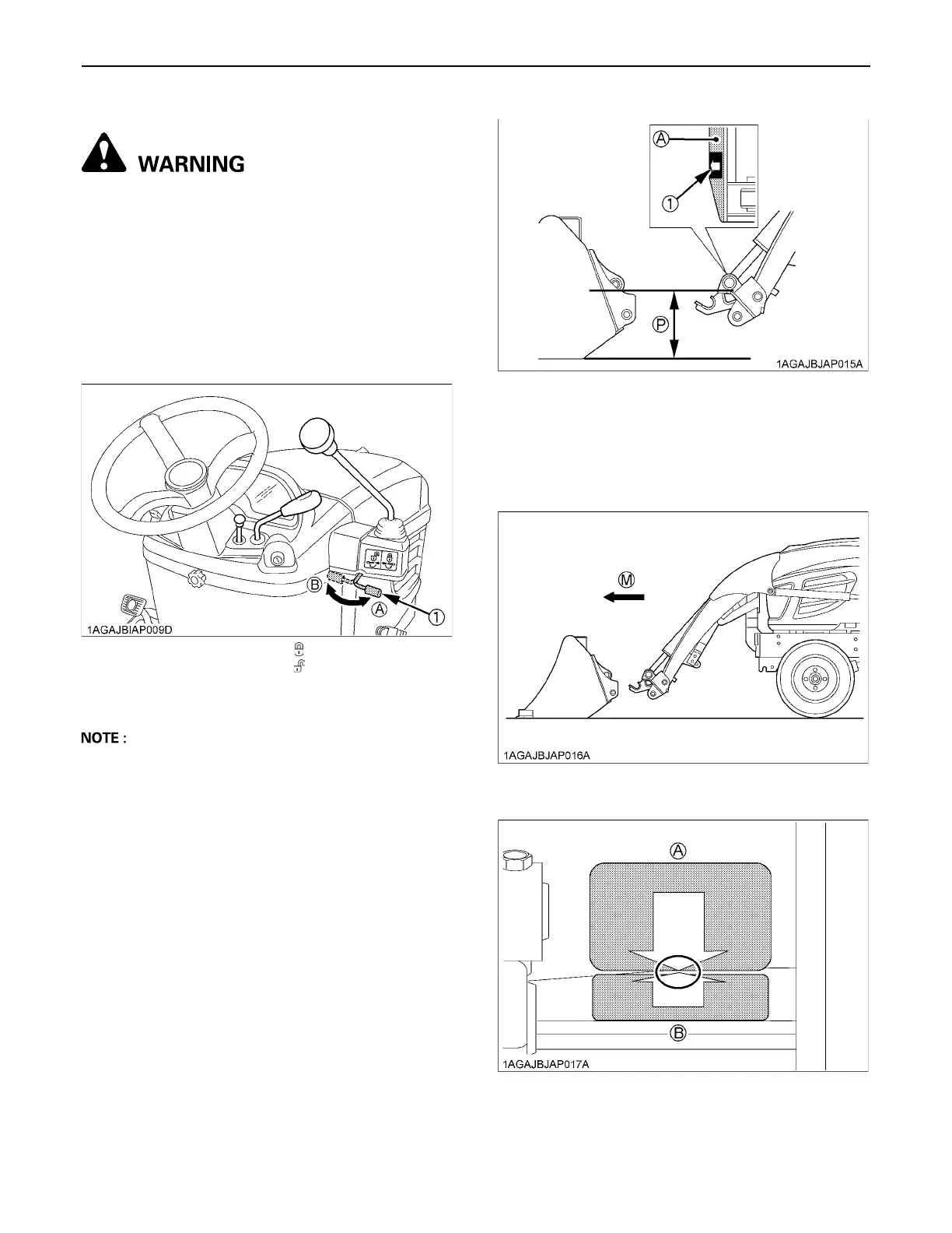
2. Move the loader control lever to the "dump" position
until the surface with the arrow marker on the BX6315
Quick Coupler label gets in parallel with the ground as
shown in the following illustration.
3. Move the tractor forward slowly until the arrow marker
on the attachment label is close to that on the Quick
Coupler label.
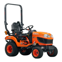
[When viewed from the operator's seat]
(1) Lock lever (A) "LOCK"
(B) "UNLOCK"
(1) Arrow marker (A) Position this surface in
parallel with the ground.
(P) "PARALLEL"
(M) "MOVE FORWARD SLOWLY"
(A) Front attachment side
(B) Quick Coupler side
 Loading...