5.1
ENGINE
BODY
92.4mm
STROKE
SERIES
WSM,01095
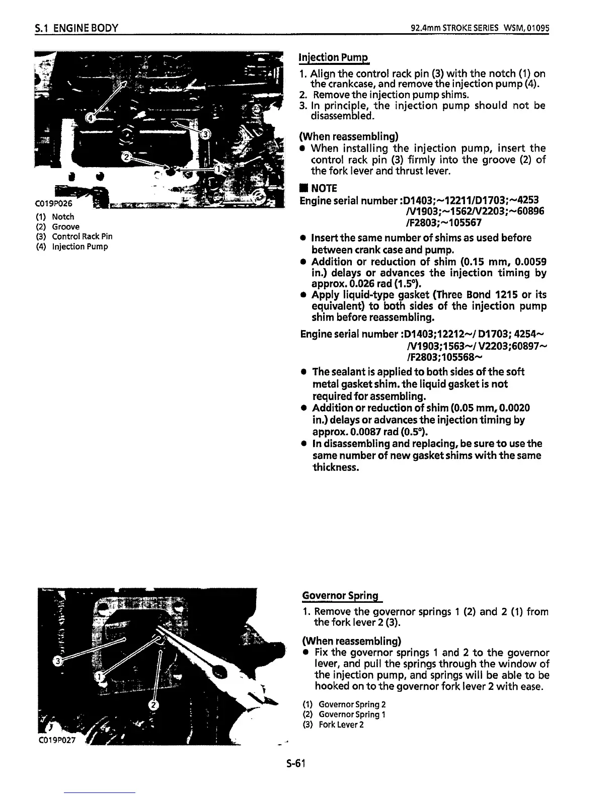
(1)
Notch
(2)
Groove
(3)
Control
Rack
Pin
(4)
injection Pump
injection Pump
1.
Align the control rack pin
(3)
with the notch
(1)
on
the crankcase, and remove the injection pump
(4).
2.
Remove the injection pump shims.
3.
In principle, the injection pump should not be
disassembled.
(When reassembling)
e
When installing the injection pump, insert the
control rack pin
(3)
firmly into the groove
(2)
of
the fork lever and thrust lever.
I
NOTE
Engine serial number
:D1403;-12211/D1703;-4253
-
N1903;-1562N2203;-60896
JF2803;-105567
insert the same number of shims as used before
between crank
case
and pump.
Addition or reduction of shim
(0.15
mm,
0.0059
in.)
delays or advances the injection timing by
approx.
0.026
rad
(1
.So).
Apply liquid-type gasket (Three Bond
1215
or
its
equivalent) to both sides of the injection pump
shim before reassembling.
Engine serial number
:D1403;12212-/ D1703; 4254-
N1903;I 563-1 V2203;60897-
lF2803; 105568-
0
The sealant
is
applied to both sides of the
soft
metal gasket shim. the liquid gasket
is
not
required for assembling.
Addition or reduction of shim
(0.05
mm,
0.0020
in.) delays or advances the injection timing by
approx.
0.0087
rad
(0.5').
0
In
disassembling and replacing, be sure to use the
same number of new gasket shims
with
the
same
thickness.
Governor Spring
1.
Remove the governor springs
1
(2)
and
2
(1)
from
the fork lever
2
(3).
(When reassembling)
0
Fix
the governor springs
1
and
2
to the governor
lever, and pull the springs through the window of
the injection pump, and springs will be able to be
hooked on to the governor fork lever
2
with
ease.
(1)
Governor Spring
2
(2)
Governor Spring
1
(3)
Fork Lever
2
S-6
1

 Loading...