5.5
ELECTRICAL SYSTEM
92.4mm STROKE
SERIES
WSM,
0109A
I
E
-
(WhitelRed) (Black)
Pull
'P
r
i
Approx.
100
rmi
if
reading
is
a,
voltage coil
is
cut.
If reading
is
0,
relay coil
is
shorted.
'
If
reading
ism,
pressure coil
is
cut
w
I
~ If reading
is
over 0, bad contact
on
voltage relay
point P2.
I
C022F046
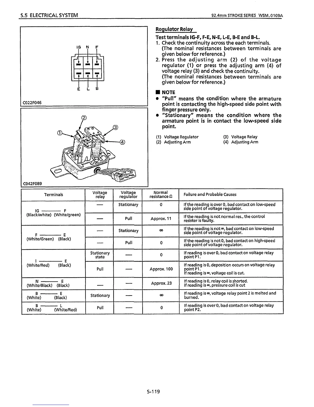
Regulator Relay
Test
terminals
IG-F,
F-E,
N-E,
L-E,
B-E
and
B-L.
1.
Check the continuity across the each terminals.
(The nominal resistances between terminals are
given below for reference.)
2.
Press the adjusting arm
(2)
of the voltage
regulator
(1)
or press the adjusting arm
(4)
of
voltage
relay
(3)
and check the continuity.
(The nominal resistances between terminals are
given below
for
reference.)
NOTE
a
"Pull"
means the condition where the armature
point
is
contacting the high-speed side point with
finger pressure only.
a
"Stationary" means the condition where the
armature point
is
in contact
the
low-speed side
point.
(1) Voltage Regulator
(2) Adjusting Arm
(3)
Voltage Relay
(4) Adjusting Arm
I- I
Stationary
I
0
IG
F
(Blackhhite) (Whitelgreen)
-
Pull Approx. 11
Stationary
F
E
(White/Green) (Black)
-I
O
I
Stationary
I
state
N-
E
I
-
1
Approx.23
(White/Black) (Black)
I-
(White) (Black)
I
Stationary
I
-I
B-E
B-
L
(White) (WhitelRed)
I
Failure and Probable Causes
I
If
reading
is
0, deposition occurs on voltage relay
ooint
PI.
I
If reading
is
00,
voltage relay point 2
is
melted and
burned.
5-1
19

 Loading...