S.l
ENGINE
BODY
92.4mm
STROKE
SERIES
WSM,0109B
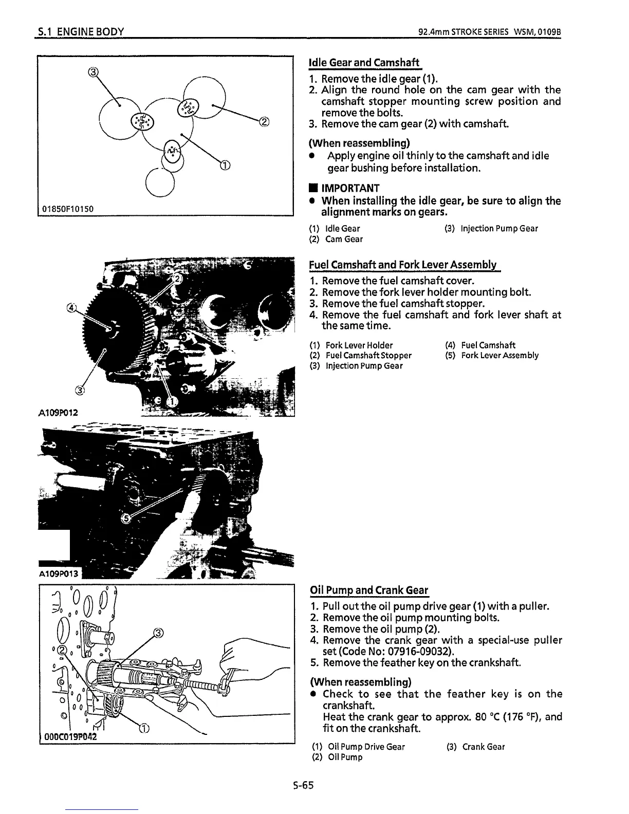
Idle Gear and Camshaft
A1
09F
OOOC019P042
1.
Remove the idle gear
(1).
2.
Align the round hole on the cam gear with the
camshaft stopper mounting screw position and
remove the bolts.
3.
Remove the cam gear
(2)
with camshaft.
(When reassembling)
0
Apply engine oil thinly to the camshaft and idle
gear bushing before instal lation.
IMPORTANT
When installing the idle gear, be sure to align the
alignment marks on gears.
(1)
IdleGear
(2) CamGear
(3)
Injection Pump Gear
Fuel Camshaft and Fork Lever Assembly
1.
Remove the fuel camshaft cover.
2.
Remove the fork lever holder mounting bolt.
3.
Remove the fuel camshaft stopper.
4.
Remove the fuel camshaft and fork lever
shaft
at
the same time.
(1)
Fork Lever Holder (4) Fuel Camshaft
(2) Fuel Camshaft Stopper
(5)
Fork Lever Assembly
(3)
injection Pump Gear
Oil
Pump and Crank Gear
1.
Pull
out the oil pump drive gear
(1)
with
a
puller.
2.
Remove the oil pump mounting bolts.
3.
Remove the oil pump
(2).
4.
Remove the crank gear with a special-use puller
5.
Remove
the
feather key on the crankshaft.
(When reassembling)
0
Check
to
see that the feather key
is
on the
crankshaft.
Heat the crank gear to approx.
80
"C
(176
OF),
and
fit
on
the
crankshaft.
set
(Code No:
0791
6-09032).
(1)
Oil
Pump Drive Gear
(3)
Crank Gear
(2)
Oil
Pump
S-6
5
 Loading...