77HYDRAULIC UNIT
To avoid damage of the attachments:
A Do not connect attachments through the hydraulic
motor to the [C] and [D] ports. If the control lever is
moved to the Regeneration position (R1), the seals on
the hydraulic motor will be damaged.
A This control valve is provided with the Regeneration
position. When the [C] and [D] ports are used to take
off hydraulic power for the hydraulic cylinder, be sure
to connect the [C] port to the "Head-End" side port of
the hydraulic cylinder.
A Make the following connections when using this valve
to take off hydraulic power for the hydraulic cylinder.
C Rear Hydraulic Outlet (if equipped)
With the optional kit in place, oil from the loader valve can
be taken out of the back of the tractor.
A With this optional kit in place, oil cannot be taken for
the front loader.
A If the optional remote hydraulic control valve is already
in place, this kit cannot be additionally installed.
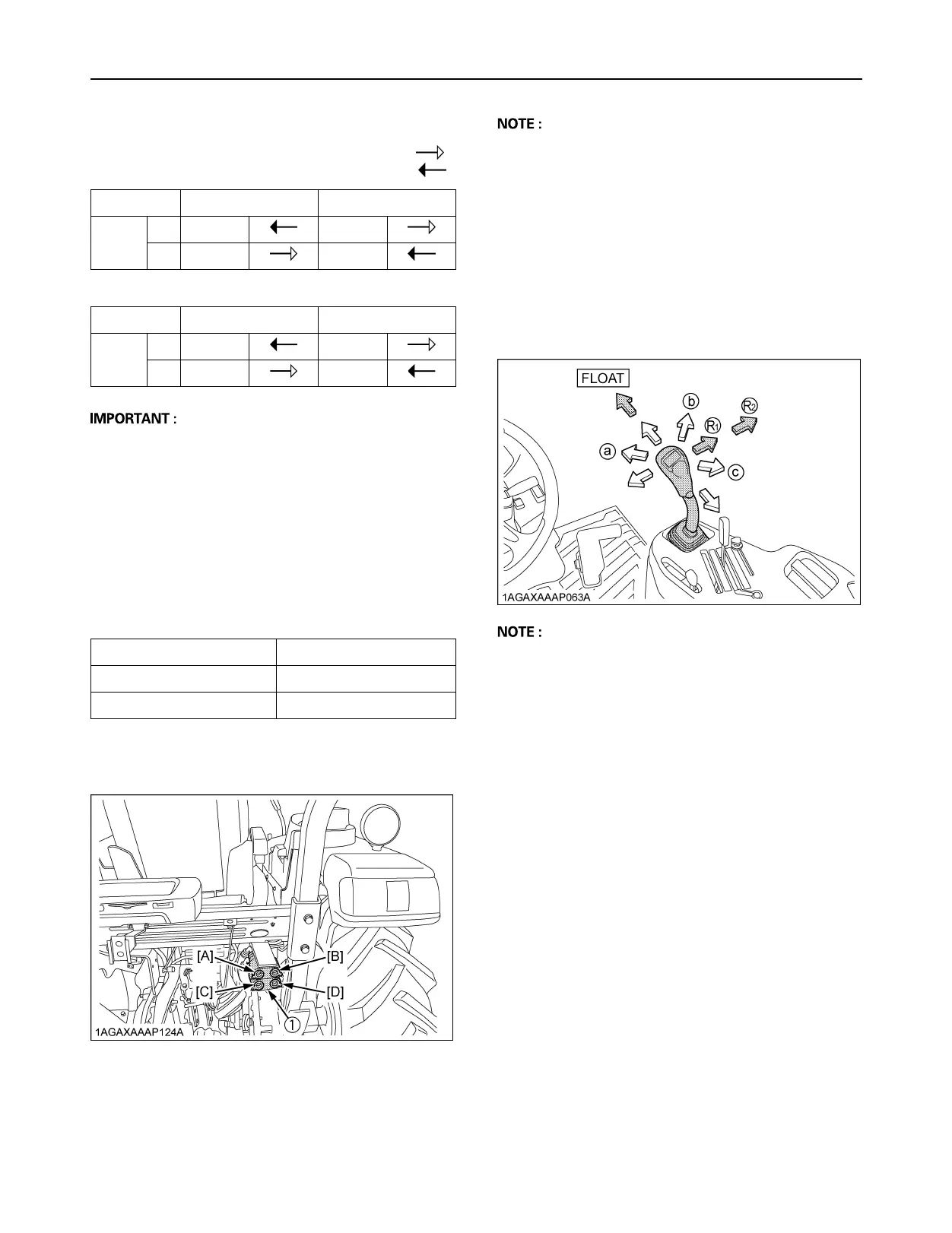
BLoader / Remote Control Valve Lever
1. Before moving the lever, make sure that the hydraulic
hoses for attachments are connected.
2. Move the lever diagonally (a, b, c shown in the figure),
and the first and second segments can be controlled
at once.
A Move the lever to the "FLOAT" position, and it will be
held there by the detent mechanism. To use the valve
as a floating valve with detents, connect the hydraulic
hoses to ports [A] and [B].
A When taking off hydraulic power from port [D], the flow
rate can be adjusted in two stages with the lever.
The flow rate is high at position (R1) and low at
position (R2). Move the lever to position (R1) or (R2)
depending on the attachment in use.
Pressure
Returning
Hydraulic outlet ports of first segment
Lever UP DOWN
Port
[A] In Out
[B] Out In
Hydraulic outlet ports of second segment
Lever RIGHT LEFT
Port
[C] In Out
[D] Out In
Colored Coupler Hydraulic Cylinder port
[B: Yellow], [C: Blue] Head-End side
[A: White], [D: Red] Rod-End side
(1) Rear Hydraulic Outlet
 Loading...