4-M6
ZD18(F) · ZD21(F) · ZD28(F), WSM
HYDRAULIC SYSTEM
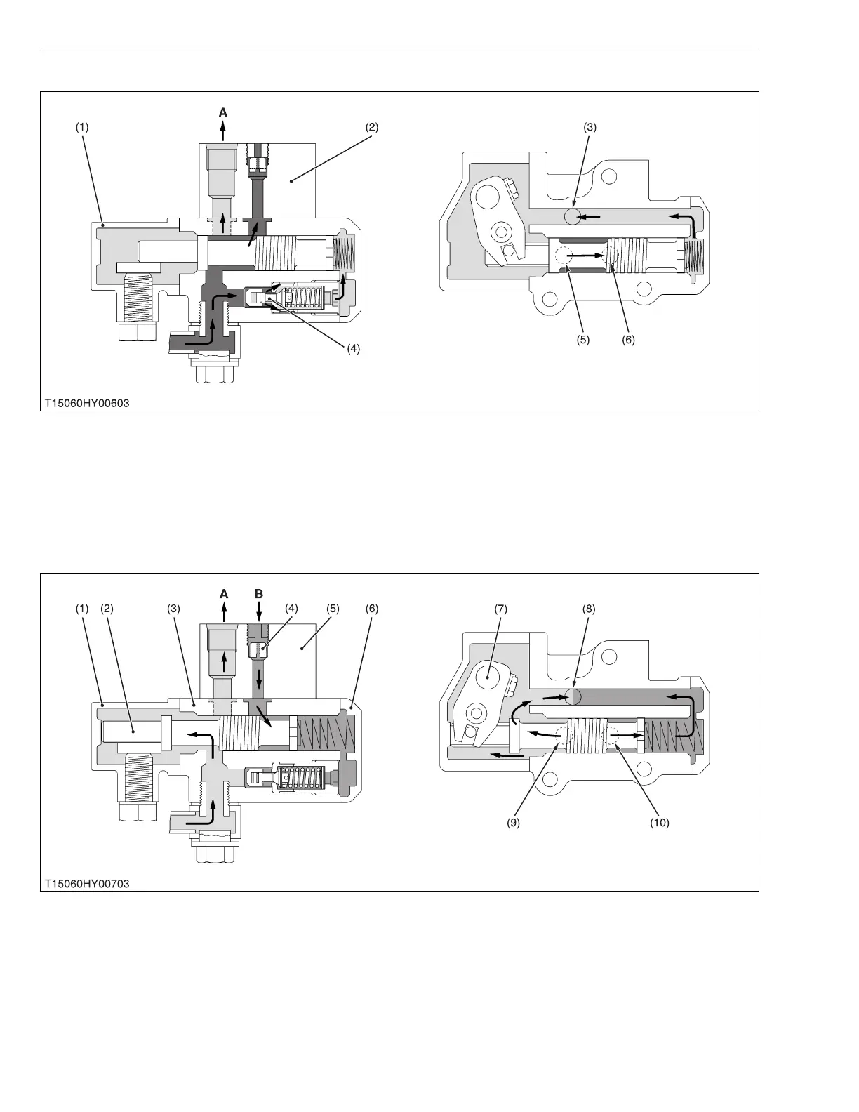
Overloaded
If the pressure in the circuit exceeds the relief valve setting pressure (3.14 to 3.73 MPa, 32 to 38 kgf/cm
2
, 455 to
540 psi), the relief valve (4) opens to release pressure-fed oil.
Then, oil flows to the hydrostatic transmission through the R port (3) and control valve adaptor (2) as shown in the
figure.
Down
When the control lever (7) is set to “DOWN” position, the spool (2) moves to the left to form a lowering circuit.
Therefore, oil in the lift cylinder is forced out by the weight of the mower and returns to the hydrostatic transmission to
lower the mower as shown in the figure.
Oil, pressure-fed from the hydraulic pump, goes through the clearance between the valve body (3) and spool (2),
and then flows to the hydrostatic transmission through the R port (8) and control valve adaptor (5).
(1) Spool
(2) Control Valve Adaptor
(3) R (Return) Port
(4) Relief Valve
(5) P (Pump) Port
(6) C (Cylinder) Port
A: To Hydrostatic Transmission
(1) Valve Cover
(2) Spool
(3) Valve Body
(4) Orifice
(5) Control Valve Adaptor
(6) Relief Cover
(7) Control Lever
(8) R (Return) Port
(9) P (Pump) Port
(10) C (Cylinder) Port
A: To Hydrostatic Transmission
B: From Lift Cylinder
 Loading...