4-S3
ZD18(F) · ZD21(F) · ZD28(F), WSM
HYDRAULIC SYSTEM
3. CHECKING, DISASSEMBLING AND SERVICING
[1] HYDRAULIC CONTROL VALVE, PUMP AND CYLINDER
(1) Checking and Adjusting
Relief Valve Setting Pressure
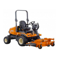
1. Remove the eye joint bolt (1) from the hydraulic.
2. Install the adaptor, cable and pressure gauge.
3. Start the engine and set at maximum speed.
4. Move the control lever to “LIFT” position to operate the relief
valve and read the gauge.
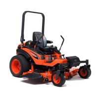
5. If the pressure is not within the factory specifications, adjust with
the adjusting shims (3).
Condition
• Engine speed …… Maximum
• Oil temperature … 45 to 55 °C
113 to 131 °F
(Reference)
• Thickness of shims (3): 0.2 mm (0.0079 in.)
0.3 mm (0.0118 in.)
0.8 mm (0.0315 in.)
W1011441
(2) Disassembling and Assembling
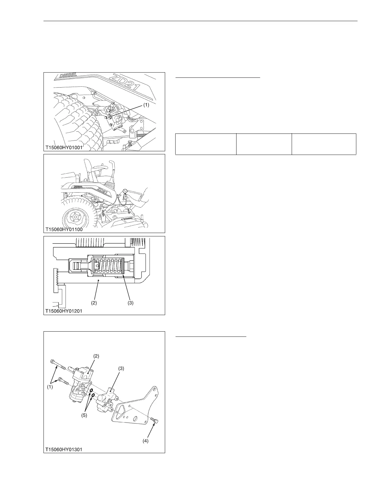
Removing Control Valve
1. Remove the control lever.
2. Disconnect the return pipe and hydraulic hose from control valve.
3. Remove the eye joint bolt from control valve then remove the
control valve and bracket as a unit.
4. Remove the control valve adaptor mounting screws (4), and
remove the control valve (2) with the control valve adaptor (3).
5. Remove the control valve mounting screws (1), and remove the
control valve from the control valve adaptor.
(When reassembling)
• Take care not to damage the O-rings (5).
W1011940
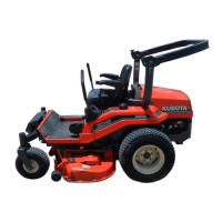
Relief valve setting
pressure
Factory spec.
3.14 to 3.73 MPa
32 to 38 kgf/cm
2
455 to 540 psi
(1) Eye Joint Bolt
(2) Control Valve Assembly
(3) Shim
(1) Control Valve Mounting Screw
(2) Control Valve
(3) Control Valve Adaptor
(4) Control Valve Adaptor Mounting
Screw
(5) O-ring
 Loading...