2T6/2T7/2T8/2T9-2
2-2-1
2-2 Electrical Parts Layout
2-2-1 Electrical parts layout
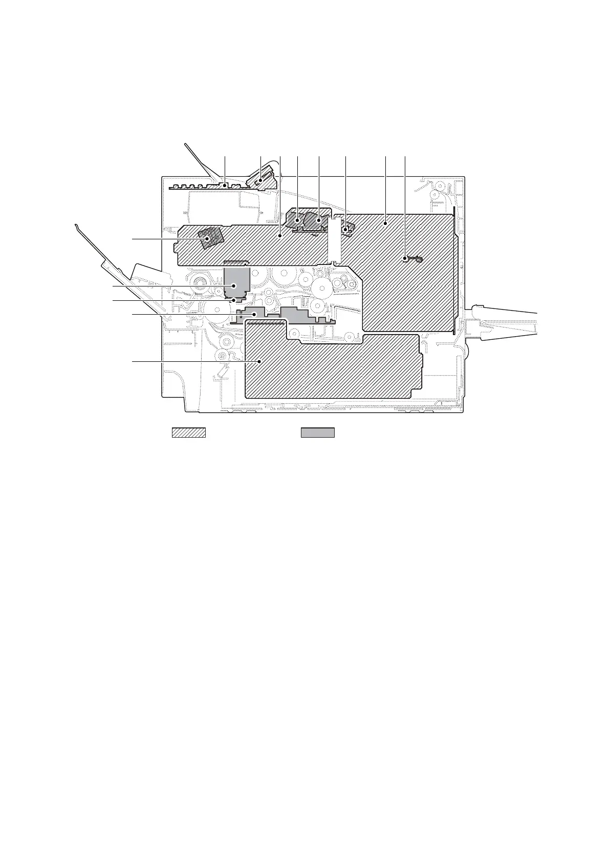
(1) PWBs
Figure 2-2-1 PWBs
1. Main PWB (MPWB) .............................. Controls the software such as the print data processing and
provides the interface with computers.
2. Engine PWB (EPWB)............................ Controls printer hardware such as high voltage/bias output con-
trol, paper conveying system control, and fuser temperature con-
trol, etc.
3. Power source PWB (PSPWB) .............. After full-wave rectification of AC power source input, switching
for converting to 24 V DC for output. Controls the fuser heater.
4. High voltage PWB (HVPWB) ................ Generates main charging, developing bias, transfer bias.
5. Drum PWB (DRPWB) ........................... Relays wirings from electrical components on the drum unit.
Drum individual information in EEPROM storage.
6. Drum relay PWB (DRRPWB)................ Consists of wiring relay circuit between engine PWB and the
drum unit.
7. Relay-L PWB (R-LPWB) ....................... Consists of wiring relay circuit between engine PWB and drum
connect PWB.
8. Operation PWB (OPPWB-M) ................ Consists the LCD, LED indicators and key switches.
9. Backlight PWB (BLPWB) ...................... LCD lighting.
10. Fuser thermistor relay PWB
(FUTHRPWB) ....................................... Consists of wiring relay circuit between engine PWB ,fuser
thermistors and cooling fans.
11. APC PWB (APCPWB) .......................... Generates and controls the laser beam.
12. PD PWB (PDPWB) ............................... Controls horizontal synchronizing timing of laser beam.
13. Container PWB (CPWB) ....................... Reads the container information.
1117 1011122
5
6
13
4
3
8 9
Machine right Machine inside
 Loading...