38
6 O
2
Trim
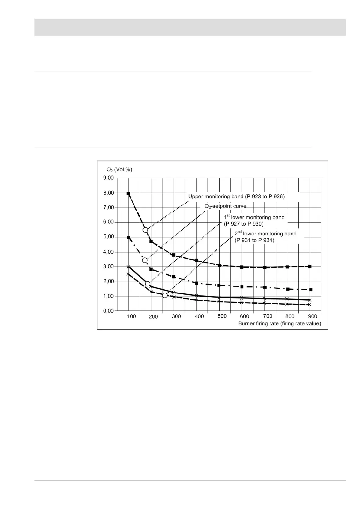
6.5.2 O
2
Monitoring Band
During burner operation, the actual O
2
value is continuously monitored for one maximum and
two minimum permissible values. These ranges are located around the O
2
setpoint as a func-
tion of firing rate. If the actual values stay outside these bands for a defined period, the control
system is deactivated and a “Fault” warning is output.
Thereafter, the control unit’s output (correction input) corresponds to “Base value without con-
trol” or “Base value with air deficiency”.
6.5.3 O
2
Limit Curve
You can set the monitoring bands’ parameters for 2 fuels, oil/gas, as a function of fuel. The
permitted deviation is calculated as a percentage of the setpoint. You can specify two separate
percentage values for base firing rate and full firing rate. The section between is interpolated
linearly.
Monitoring/shutdown times:
1
st
monitoring band: 120 seconds; active after “Control on”.
2
nd
monitoring band: 30 seconds; active after “Burner on”.
Factory setting
1
st
monitoring band, upward direction
– Base firing rate (parameters 923 / 925) 60%
– Full firing rate (parameters 924 / 926) 100%
1
st
monitoring band, downward direction
– Base firing rate (parameters 927 / 929) 40%
– Full firing rate (parameters 928 / 930) 50%

 Loading...
