46
8 Options
8.2 Digital Outputs via LSB Module, LSB Address 03 and 51
8.2.1 Functional Description
• 4 relay outputs 250 VAC, 6 A.
• Possible to quickly wire several modules by means of jumper plugs.
• The relay outputs are activated manually using switches.
LSB modules are universally applicable output modules for DIN rail mounting. They are actu-
ated via the LSB. The module is addressed via a settable address (1 ... 99). The data bytes
transmit whether data is required or commands are to be executed.
NOTICE
All outgoing lines from the LSB module must be shielded. The shields must be applied to the
PE rail as short as possible.
NOTICE
The termination resistor (120 ) must be installed and activated on the first and the last BUS
device.
Avoid stub line!
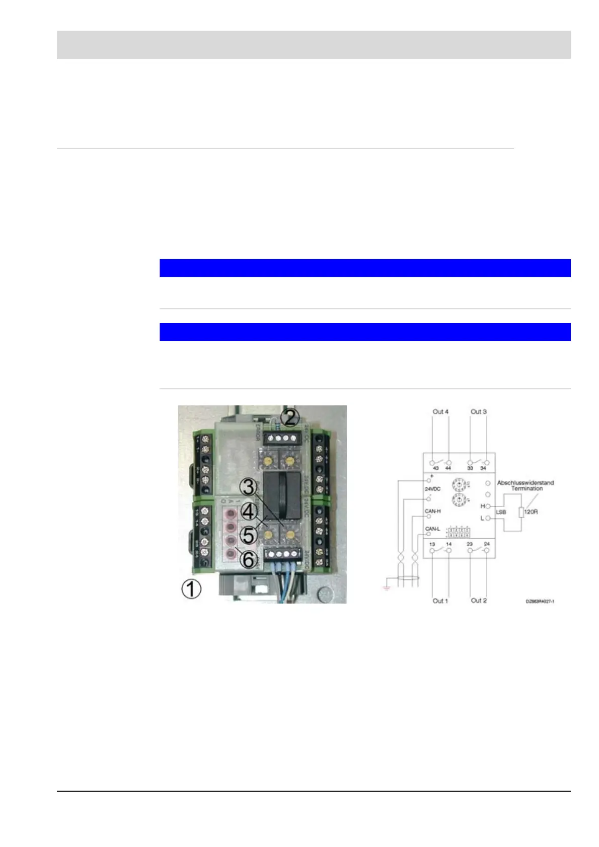
1 Digital output module Terminal assignment:
2 LSB terminal resistance 120 13/14 Relay output 1
3 Rotary switch for setting the
tens LSB address
23/24 Relay output 2
4 Rotary switch for setting the ones
LSB address
33/34 Relay output 3
5 LSB Bus Connector Plug 43/44 Relay output 4
6 Manual activation 24 VDC Voltage supply for LT3 Termi-
nals 77-/78+
CAN H/L LAMTEC SYSTEM BUS for LT3
Terminals 74 H/75 L
 Loading...
