Development Kit
XPort™ Integration Guide 17
Table 3-2. Configuration Switch Settings
SW1 POS Function
ON SW1-1 and SW1-6 ON for self-test mode. (Factory test)
1
OFF Normal mode.
ON SW1-1 and SW1-6 ON for self-test mode. (Factory test) 6
OFF Normal mode.
OFF XPort CP1/RTS (pin 6) is connected to the RS-232 transceiver, which
connects to the CTS of an attached device through DB9 pin 8. Use this setting
if CP1 is set up for hardware flow control.
2
ON XPort CP1/RTS (pin 6) is not connected to an RS-232 transceiver. Use this
setting if CP1 is set up as an IN1, OUT1, or LED1.
OFF XPort CP2/DTR (pin 7) is connected to the RS-232 transceiver, which
connects to DCD of an attached device through DB9 pin 1. Use this setting if
CP2 is set up for hardware handshaking.
3
ON XPort CP2/DTR (pin 7) is not connected to the transceiver. Use this setting if
CP2 is set up as an IN2 or OUT2.
OFF Use this setting when XPort CP3/CTS/DCD (pin 8) is set up for hardware
handshaking. With SW1-5 configured appropriately, CP3 will connect to DTR
of an attached device.
4
ON Use this setting when XPort CP3/CTS/DCD (pin 8) is set up for hardware flow
control. With SW1-5 configured appropriately, CP3 will connect to RTS of an
attached device.
OFF XPort CP3/CTS/DCD (pin 8) is connected to the RS-232 transceiver, which
connects to either the DTR (DB9 pin 4) or the RTS (DB9 pin 7) of an attached
device, depending on the setting on SW1-4. Use this setting if CP3 is set up
for hardware flow control.
5
ON XPort CP3/CTS/DCD (pin 8) is not connected to the transceiver. Use this
setting if CP3 is set up as an IN3, OUT3, or LED3.
SW1-2 Options
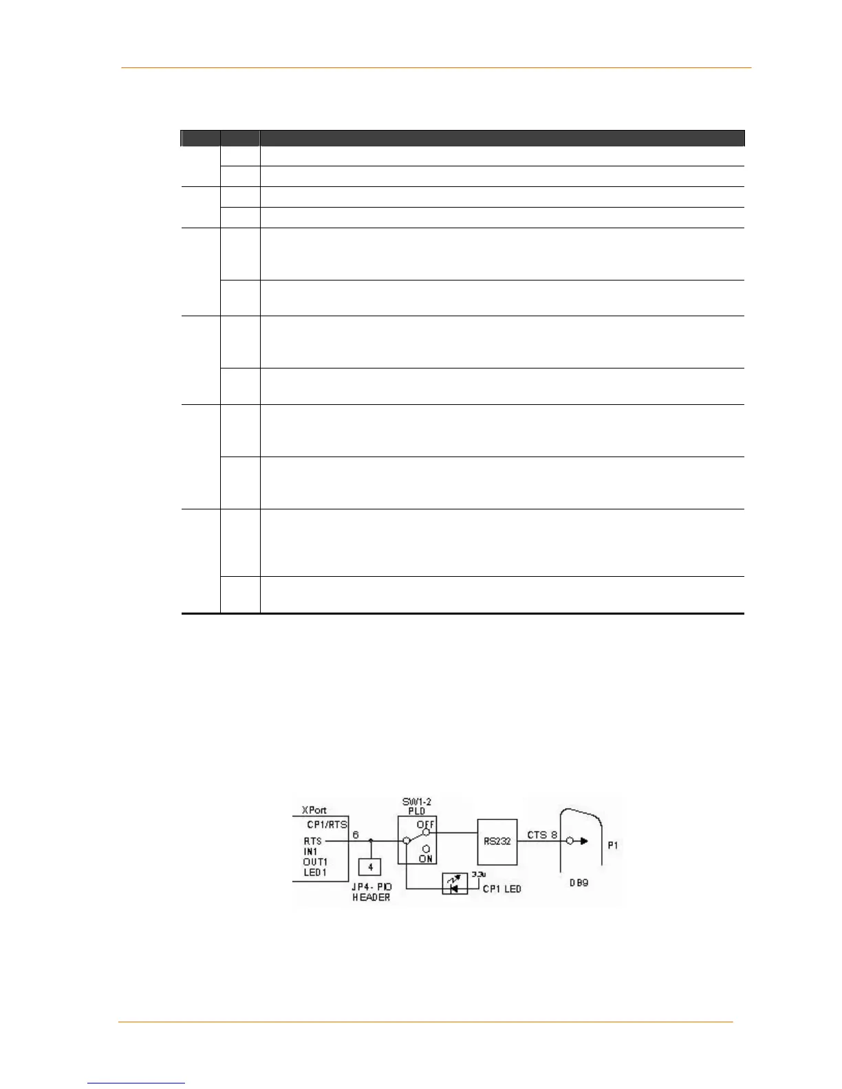
SW1-2 controls the routing of the CP1/RTS (configurable pin 1) signal from the
XPort. CP1 is connected to pin 6 of the XPort and can be software configured as
CTS, IN1, OUT1, or LED1. SW1-2 is an input to the PLD, which does the actual
switching. The drawings represent the logical switching function.
In this drawing, SW1-2 is OFF, which connects XPort pin 6 to the RS-232
transceiver. The XPort configurable pin 1 (CP1) is configured for CTS.
Figure 3-1. SW1-2 OFF
In the next drawing, SW1-2 is ON, which disconnects pin 6 from the RS-232
transceiver. The XPort configurable pin 1 (CP1) is configured for LED1.
 Loading...