Development Kit
18 XPort™ Integration Guide
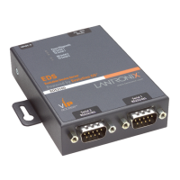
Figure 3-2. SW1-2 ON
When configurable pin 1 is configured for LED1, it functions as a status indicator for
the serial port.
Table 3-3. CP1 Status Indicator
Condition CP1 LED State
Idle channel Solid on
Connected to network 4 blinks every 4 seconds
CTS and RTS work together for hardware flow control. Configure CP3 as RTS when
CP1 is configured as CTS. Select hardware flow control as described in Flow in the
XPort User Guide. See the Device Installer User Guide for information on configuring
CP1 as IN1 or OUT1.
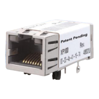
SW1-3 Options
SW1-3 controls the routing of the CP2/DTR (configurable pin 2) signal from the
XPort. CP2 is connected to pin 7 of the XPort and can be software-configured as
DCD, IN2, or OUT2. SW1-3 is an input to the PLD that does the actual switching. The
drawings represent the logical switching function.
In this drawing, SW1-3 is OFF, which connects XPort pin-7 to the RS-232
transceiver. The XPort CP2 is configured for DCD.
Figure 3-3. SW1-3 OFF
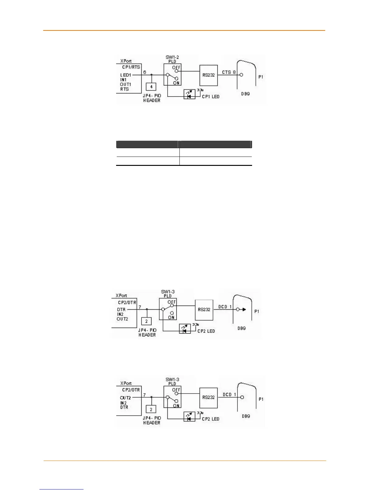
In the drawing below, SW1-3 is ON, which disconnects XPort pin-7 from the RS-232
transceiver. The XPort CP2 is configured for OUT2.
Figure 3-4. SW1-3 ON
See the Device Installer User Guide for information on configuring CP2 as IN2 or
OUT2.
 Loading...